Trusted Dallas Machine Shop For Precision Parts Manufacturing

Surprising fact: more than 70% of critical industrial failures can be traced to a single part that drifted বাইরে tolerance by less than 0.5 mm. Lowrance Machine delivers focused Lowrance Machine Dallas solutions designed to reduce that risk. Our team uses tested machining practices and tight inspection routines to keep parts within tight tolerances. This reduces downtime, supports consistency, and strengthens production reliability for U.S. manufacturers.

Lowrance Machine CNC Machining in Dallas
With deep experience in custom component work, we machine parts and products that fit each client’s operating environment. Go to www.lowrancemachine.com to learn how our experienced team and precision equipment create dependable parts that satisfy engineering specs and help you reach production targets.

Important Takeaways

  • Precision components reduce expensive failures and keep lines running smoothly.
  • Lowrance Machine Dallas Services focus on repeatability and tolerance accuracy.
  • Experienced staff apply advanced machining methods to produce dependable products.
  • Every part is inspected to satisfy strict engineering standards.
  • See www.lowrancemachine.com for tailored machining solutions that fit your production goals.

How Lowrance Machine Delivers Precision Engineering

At the center of our shop, precision engineering turns complex drawings into dependable parts. Our team concentrates on close tolerances and repeatable processes so every finished part matches the assembly it was designed for.

Quality is more than a claim in our shop; it is part of our daily routine. We blend real shop-floor experience with calibrated equipment to meet the needs of the businesses that count on our work.

  • Customized solutions built around project requirements and production schedules.
  • Routine inspections that support dependable product quality for every customer.
  • Experienced machinists who apply years of knowledge at every station.
  • Explore www.lowrancemachine.com to see how our service can strengthen production uptime.

Our shop offers straightforward communication, fast turnaround, and engineered answers that reduce operational risk. Choosing our shop means you get components that hold up when performance counts.

Lowrance Machine Precision Machining in Dallas

Comprehensive Lowrance Machine Dallas Services

Lowrance Machine delivers a full range of precision machining services designed to help you meet production targets. You can call (281) 449-6524 or visit www.lowrancemachine.com to talk through schedules, pricing, and project details.

We have spent years refining processes for varied materials and complex parts. This practical experience allows customers to cut lead times, lower rework, and keep production more consistent.

Our quality tracking follows strict metrics, much like the disciplined reporting periods used by regulated businesses. The result is more consistent output and more predictable performance for your operation.

Reach out through www.lowrancemachine.com to find out how our machining services can support your toughest production demands.

CNC And Manual Machining Capabilities At Lowrance Machine

By combining CNC accuracy with hands-on manual skill, we can handle complex components with confidence. The result is a machining process that balances efficiency with detailed control.

We rely on advanced cnc manual workflows to make sure each component meets drawing tolerances. Digital programming is paired with skilled manual setup to create tight, repeatable outcomes.

Our machine shop works with many materials, including aluminum, stainless steel, and engineering plastics. Because of that material flexibility, we can manufacture molds, prototypes, and production parts to spec.

Go to www.lowrancemachine.com to review how our CNC manual workflow delivers flexible machining solutions across different sectors.

We maintain a state-of-the-art shop where manual skill and modern control systems work together. The benefit is shorter lead times, better first-run success, and more dependable overall output.

Machining Capability Supported Materials Typical Output
Precision CNC milling and turning Aluminum, brass, and steel Precision components, molds
Manual finishing & setup Engineering plastics and composites Prototypes, low-volume runs
Quality assurance & inspection Every supported material Certified lots and measured parts
  • A blended CNC-manual process that supports difficult geometry and strict tolerance work.
  • Material flexibility that supports both design intent and performance goals.
  • Explore www.lowrancemachine.com for examples of our work and direct contact details.

Commitment To Quality And Innovative Design

We pair innovative engineering with measurable quality systems to deliver parts that perform in the field. The result is a process that respects both the drawing and the realities of production.

Lowrance Machine manufactures carefully designed and engineered products across a wide range of sizes. Each finished product is intended to give businesses dependable fit, proper function, and long service life.

Our company draws on years of experience to expand design capability and serve diverse customer requirements. Our investment in talent and tools helps customers receive stronger quality outcomes.

Explore www.lowrancemachine.com to see real project examples and how our quality standards guide every product we manufacture.

Modern Equipment And Processing Techniques

Our shop embraces newer processing methods so every job is matched with the proper tooling, setup, and workflow. Lowrance Machine invests in current systems to provide fast, precise work and practical solutions across industries.

Our machine shop blends advanced cnc centers with skilled manual setups. This combination allows us to machine high-quality molds and parts on tight schedules.

Each machine is calibrated and maintained to preserve tolerance accuracy. We follow validated workflows to help hit quality targets on the first pass.

“The right tools and the right techniques help our clients achieve consistent, measurable results.”

  • Modern shop floor equipped with calibrated tools and maintained systems.
  • A hybrid CNC-manual process designed for repeatability and part consistency.
  • Transparent information and project examples at www.lowrancemachine.com.
Equipment Primary Process Typical Result
Modern CNC mills and lathes Programming & automated runs Close-tolerance components
Dedicated manual workstations Finishing & setup Prototypes and lower-volume mold work

How We Serve Diverse Industry Needs

Our team partners with manufacturers to provide quality parts and products that address specific production problems. Our service model emphasizes clear communication and delivery performance that customers can plan around.

Lowrance Machine adapts its machining capabilities to meet the needs of different industries. Our machinists work across many materials to produce durable molds, prototypes, and production parts.

“We fine-tune every production run so customers get the right part, on schedule, and to the exact spec they count on.”

  • Flexible capabilities for both low-volume prototypes and high-volume production products.
  • Material knowledge that helps align the machining process with component demands.
  • Customer-focused service that adapts to unique production constraints.
Served Industry Typical Materials Typical Applications
Aerospace Stainless steel and aluminum Close-tolerance components
Medical manufacturing Medical plastics and titanium Precision molds & parts
Industrial sector Alloy steels with composite materials Durable production components

Go to www.lowrancemachine.com to learn how our service-driven process and optimized machine setups handle complex Dallas-area work.

Partnering With Our Dallas Machining Experts

Work with a machining partner that offers clear plans and practical solutions that keep your production on track. That focus helps your business reduce downtime, improve consistency, and support stronger part performance.

The machine shop operates with both advanced CNC capability and proven manual machining skill. Our team delivers a professional machining service centered on quick quotes, thorough quality checks, and efficient production workflows.

Working with Lowrance Machine gives your business access to extensive experience and tailored machining services at www.lowrancemachine.com. Our aim is to be a dependable ally for future jobs, current production goals, and long-term growth.

Visit www.lowrancemachine.com to discuss how our machining team can help your business achieve its goals with reliable, precision-focused solutions.

Dual-Density Ribbon Production on a Fiber Ribbon Line

Might the machines manufacturing fiber optic cable production machinery act as the unseen force that finally brings true gigabit access to every American home? This article delves into the recent breakthroughs in FTTH Cable Production Line Technology. These advancements are reshaping broadband network infrastructure and accelerating fiber to the home technology across the United States.

SZ Stranding Line

FTTH Cable Production Line

Compact Fiber Unit

Modern advancements in automation, precision engineering, and AI-driven inspection are significantly reducing production costs and enhancing quality. This synergy makes high-speed internet technology more dependable and simpler to roll out for service providers and municipalities.

Global optical cable output now exceeds hundreds of millions of kilometers annually. This surge is driven by 5G deployments, hyperscale data centers, and the growing demand for streaming and remote work. The subsequent sections will delve into automation and Industry 4.0, the use of low-loss materials, AI quality control, innovative cable designs such as bend-insensitive fiber and flat drop microcables, and the pursuit of sustainability in production lines.

Telecommunications manufacturing, network planning, and procurement professionals will discover valuable insights. These insights are on selecting the right fiber optic cable production machinery and optimizing processes. They are designed to meet regional deployment needs and future bandwidth growth.

FTTH Cable Production Line Technology

The term encompasses the machinery, control systems, and materials transforming optical preforms into deployable fiber cables. It encompasses fiber drawing and coating, SZ stranding, ribbon formation, extrusion of jackets, armoring, taping, automated testing, and final take-up systems. Each step’s precise control defines the fiber optic cable production process, ensuring consistent performance.

The manufacturing chain demands stringent tolerances. SZ stranding systems align dozens of strands with micron-level tension precision. Extrusion lines employ servo-driven extruders and laser micrometers to maintain jacket thickness within ±0.02 mm. Such precision minimizes variability, lowering attenuation and making field splicing easier.

Standards and regulatory frameworks heavily affect manufacturing decisions. Compliance with ITU-T recommendations, such as G.657, and regional fire codes like CPR in Europe, is essential. Meeting these standards ensures products align with the broader broadband network infrastructure.

Quality in production directly impacts network economics and service delivery. Lower attenuation and consistent geometry reduce splice loss and extend reach. This enhances reliability for carriers, ISPs, and utilities, while lowering the total cost of ownership for FTTH deployments. The growing demand for symmetrical multi-gigabit services, 5G backhaul, and data center interconnect is driving the scale-up of modern lines.

Comparing key process components and tolerances reveals their impact on output and quality.

SZ Stranding Line

Process Component Typical Control Effect on Performance
Fiber draw and coating Temperature stability ±1°C; concentricity control ±5 µm Stable fiber profile; lower bending-related loss
Ribbon formation and SZ stranding Tension control at micron scale; synchronization to 0.5 ms Consistent fiber pitch; reliable splice and connector behavior
Jacket extrusion and thickness control Laser micrometer feedback; ±0.02 mm tolerance Consistent mechanical protection; predictable installation behavior
Armoring & taping Servo feed rate; layer alignment control Better crush resistance; meets aerial and underground specs
Automated testing and take-up Line-speed OTDR and insertion-loss checks; tension-controlled winding Fully traceable quality; less rework and fewer field failures

Manufacturers like Corning, Prysmian Group, and Sumitomo Electric focus on tighter process control to meet operator expectations. Continuous advancements in the fiber optic cable production process enable networks to scale while maintaining performance in the last mile of broadband network infrastructure.

Automation And Industry 4.0 In Fiber Optic Cable Production

Factory floors for fiber optic cable production machinery now mirror advanced manufacturing plants from other industries. Smart controls, synchronized stages, and data-driven decision making raise output and protect quality. These shifts shorten commissioning time for new product families. They let telecommunications equipment manufacturers pivot between armored aerial lines and microcable runs with minimal downtime.

Smart machinery and PLC coordination

Programmable logic controllers coordinate stranding frames, ribbon formers, and take-up units to keep tension within sub-0.01mm windows. Servo-driven extrusion coupled with laser micrometers enforce ±0.02mm jacket thickness. The result is fewer rejects, less rework, and consistent optical performance on every reel.

Edge processing and process coordination

Local edge servers ingest terabytes of telemetry each day. They drive low-latency closed-loop adjustments and push immediate alerts when deviations occur. This approach keeps optical fiber cable equipment running at peak efficiency. It supports real-time quality assurance during long production runs.

AGVs, material flow, and workflow gains

Automated Guided Vehicles move heavy cable drums with millimeter-level repeatability. Laser-navigated AGVs reduce manual handling injuries and speed material flow between extrusion, curing, and drum stations. This automation lowers labor costs while raising throughput on ftth cable production line technology setups.

Benefits for makers and the supply chain

  • Increased throughput with consistent results
  • Quicker prototyping and a shorter path to market
  • Lower labor exposure and reduced operating cost
  • Better integration between optical fiber cable equipment and enterprise systems

Adoption across the industry ecosystem

Leading telecommunications equipment manufacturers pair PLCs with robotic arms, AGVs, and industrial IoT stacks to reach Industry 4.0 goals. This integration creates a resilient production base. It is able to adapt as demand shifts toward denser, more complex FTTH offerings.

Precision Engineering Breakthroughs For Lower Attenuation

Advances in materials and mechanical design are driving down loss in modern fiber lines. Engineers pair ultra-low loss fiber with tighter coating control to reduce intrinsic and bending attenuation. These gains matter to network operators who want longer spans and fewer amplifiers in high-speed internet technology deployments.

The fiber optic cable production process now favors smaller coated diameters such as 180µm and 160µm. These sizes let manufacturers increase fiber count and build denser microcables without sacrificing handling or optical stability.

Low-Loss Glass And Advanced Coatings

Manufacturers use improved glass formulations that lower Rayleigh scattering and reduce baseline attenuation. Ultra-low loss fiber variants extend reach for long-haul and high-capacity links while easing repeaters and amplifier requirements.

Coating chemistry has progressed too. UV-cured acrylate systems cut microbending loss by roughly 40% compared with earlier generations. That performance drop helps maintain signal integrity in cramped ducts and tight bends common in FTTH and 5G backhaul networks.

Central Strength Members And Mechanical Design

Mechanical design updates center on robustness and dimensional control. Fiber-reinforced plastic (FRP) rods with tensile strengths near 1.2 GPa serve as central strength members. They limit elongation during pulling and boost crush and bending resilience.

Water-blocking advances use swellable yarns and grease-free gel compounds to achieve near-complete moisture resistance. These measures protect optical paths and raise in-service reliability for cable installations in challenging environments.

These precision engineering steps integrate directly into fiber optic cable manufacturing workflows. When the production line aligns glass, coating, and mechanical specs, attenuation falls and networks gain reliability. That alignment shortens time to service for operators deploying modern broadband and high-speed internet technology.

Quality Control 4.0 And AI-Powered Inspection

Smart factories for fiber optic cable production now embed inspection systems that run continuously. These systems combine machine vision, machine learning, and automated testers to watch every reel and spool. The result is tighter feedback during the fiber optic cable production process and fewer surprises in the field.

AI models score coating uniformity, microbends, and surface defects at line speed. They cross-reference process telemetry from fiber optic cable production machinery and predict deviations hours before a reel moves to final spooling. This allows for in-line adjustments without stopping the line.

Automated OTDR integration performs 100% attenuation testing on every length. Modern OTDR systems using 1550nm sources map loss across reels and flag changes as small as 0.01 dB/km. Inline OTDR logs feed edge analytics for rapid root-cause tracing when a batch shows anomalies.

Robotic bend-radius simulators apply repeated stress cycles while monitoring macrobend loss. These testers validate compliance with ITU-T G.657 and customer bend specifications by running controlled bends at multiples of the cable diameter. Test outcomes are tied to batch IDs for traceability.

Thermal cycling chambers stress jackets and splices across wide temperature ranges. Environmental tests up to +85°C and down to -60°C confirm stability for extreme climates. Automated logs record each chamber run and link results to production lots.

Quality control 4.0 reduces returns and field failures by making 100% in-line testing routine. Edge analytics and OTDR integration shorten diagnosis times and improve regulatory compliance. Broadband operators see fewer truck rolls and better lifecycle performance for FTTH networks.

Cable Design Innovations For FTTH Deployments

New cable designs address common field challenges in fiber to the home technology. Engineers focus on durability, space economy, and speed of activation. These trends reduce installation time and lower long-term operational costs.

Bend-Insensitive Fiber Benefits For MDUs And Tight Routing

Bend-insensitive fiber maintains signal strength when routed around corners and through confined spaces. ITU-T G.657 compliant fibers minimize attenuation at tight radii, protecting links in multi-dwelling units and behind baseboards. Prysmian’s BendBright family and BendBrightXS exemplify how smaller coated diameters facilitate routing without compromising optical performance.

Flat Drop And Microcable Options For Flexible Deployments

Flat drop cable remains a preferred choice for aerial self-support, duct installs, and direct burial in North America. Its profile accommodates narrow pathways and enhances aerial spans with appropriate clamps. High-fiber-count flat drops necessitate enhanced radial strength and more robust hardware for longer spans.

Microcable technologies reduce outside plant profiles to 8 mm or less. Microcables and air-blown systems enable capacity addition inside existing ducts and congested corridors. These approaches reduce civil works, lower labor costs, and facilitate incremental network growth for urban and campus builds.

Pre-Connectorized Solutions To Speed Field Activation

Pre-connectorized solutions offer factory-terminated, plug-and-play assemblies that minimize field fusion and connector errors. Hardened outdoor connectors and vendor offerings like Prysmian’s ezDROP simplify mass rollouts and enhance first-pass yield. Service teams experience fewer truck rolls and faster service turn-up for smart city and 5G edge projects.

Design Main Benefit Typical Application Deployment Factor
Bend-insensitive fiber Reliable performance at tight radii MDUs, indoor routing, mini-pathways Use ITU-T G.657 fiber variants for indoor routing
Flat drop Versatile installation modes Aerial drops, direct burial, duct insertion Use correct clamps and hardware for radial strength
Microcable technologies Small footprint and incremental capacity Microduct installs, congested urban ducts Air-blown systems need compatible blower tools
Pre-terminated solutions Faster field activation and fewer errors Large deployments, rapid activation Standardized connector interfaces should be planned for

Sustainability And Energy Efficiency In Production Lines

Manufacturers in the fiber optic cable industry are embracing greener practices to reduce costs and meet consumer demands. Facilities prioritizing sustainable production witness improvements in operational efficiency and brand reputation. These advancements impact power systems, cooling, raw materials, and waste management.

Energy recovery strategies are becoming prevalent on extrusion lines and take-up reels. Regenerative braking on motor-driven spools returns power to the grid, thereby lowering net consumption. Studies indicate that energy recovery can reduce drive energy use by up to 32 percent in retrofitted reels.

Closed-loop cooling and chiller-less extrusion systems are reducing water demand. Adiabatic cooling can decrease water use by as much as 75 percent, particularly beneficial in water-scarce areas. Plants employing closed-loop cooling systems, in conjunction with heat exchangers, maintain temperature control while reducing utility expenses.

Recyclable jacket materials are transforming the disposal of cables. New polypropylene-based and modified polymer compounds meet mechanical and fire-safety standards, enabling higher recycling rates. Suppliers like Borealis and LyondellBasell are developing compounds that support the circular economy in cable jackets.

Process optimization minimizes scrap before recycling. Precision extrusion, in-line laser measurement, and real-time analytics reduce off-spec runs. Digital twins enable engineers to refine parameters, enhancing batch yields and reducing material waste.

Regulatory pressures and corporate ESG goals are compelling operators to favor vendors with transparent sustainability metrics. Municipal procurement teams and large network operators increasingly consider lifecycle impacts when selecting suppliers.

Focus Area Typical Improvement Main Benefit
Regenerative reel drives Up to 32% energy reduction Reduced electricity costs and lower peak demand
Closed-loop cooling / adiabatic systems Water use reduced by ~75% Lower water expenses and better compliance in arid areas
Recyclable outer-jacket materials Higher post-consumer recycling rates Better circularity and simpler end-of-life handling
In-line inspection and digital twins Noticeable double-digit reductions in scrap and off-spec output Better yield, less material waste
Sustainability reporting and certifications Better standing in procurement A competitive edge with network operators

Implementing these measures enhances the resilience of fiber optic cable manufacturing. It leads to lower lifecycle costs and easier compliance. Manufacturers integrating energy recovery and recyclable jacket materials position themselves for growth in the green procurement market.

Emerging Technologies Shaping Cable Manufacturing

New technologies are transforming the design and operation of fiber optic cable production machinery. These innovations expedite commissioning, diminish prototyping cycles, and empower manufacturers to test process alterations without halting production.

Digital twins create virtual replicas of entire production lines and novel cable designs. Engineers at Corning and Prysmian leverage these models to validate footprint, material flow, and layout before physical construction. Studies indicate commissioning can be up to 60% swifter when teams execute virtual scenarios and optimize layouts beforehand.

Digital twins facilitate expedited R&D for bespoke items such as armored variants and anti-rodent jackets. Virtual testing minimizes the necessity for physical prototypes and accelerates market entry. Teams can simulate process modifications, observe material interactions, and refine equipment parameters in a risk-free milieu.

AI systems introduce predictive capabilities on the factory floor. Machine learning scrutinizes 50+ parameters to forecast failures and quality deviations hours in advance. This AI predictive maintenance lessens unplanned downtime and elevates overall equipment effectiveness for high-volume lines.

Manufacturers like Siemens and ABB integrate AI with edge computing, enabling models to operate proximal to machines. Alerts prompt targeted inspections, spare part staging, and corrective actions before a fault halts production. This strategy maintains yield and shortens mean time to repair.

Quantum fiber sensing and distributed monitoring extend capabilities beyond production to the deployed cable. Embedded Brillouin and distributed acoustic sensing provide continuous strain and temperature data across extensive spans.

Integration of quantum fiber sensing enhances network diagnostics and supports structural health monitoring. Field teams acquire actionable insights when sensing data is linked to manufacturing records and test logs. This connection enables tracing anomalies to specific production batches.

Combined workflows—digital twins plus AI predictive maintenance—accelerate both commissioning and product development. Manufacturers embracing these tools can respond more swiftly to market fluctuations and deliver higher-value, differentiated cables.

Market-Driven Production Adaptations And Regional Needs

The global demand for fiber access compels manufacturers to adapt their production lines to local requirements. Regional fiber optic cable manufacturing now emphasizes durability, density, and safety. Plants employ modular equipment, enabling swift transitions between product families and meeting specific operator needs without significant delays.

In North America, networks predominantly opt for aerial routes and robust outside-plant solutions. Producers concentrate on creating armored aerial cables with enhanced breaking strength, corrosion-resistant armor, and simplified pole-mount installation. These designs withstand wind, ice, and long span stresses typical of utility corridors.

North American Priorities: Aerial And Armored Designs

Armored aerial cables are engineered for enduring reliability on poles and open spans. They boast 1,200 lb or greater tensile ratings and integrated steel or aluminum armoring to safeguard fibers against mechanical damage. Manufacturers deploy modular armoring units and rapid testing rigs, enabling mass production of these variants.

APAC And Europe: High-Density Microcables And Regulatory Compliance

In APAC, the scarcity of space and the need for dense builds drive demand for high-density microcables. These cables feature compact stranding towers and reduced-diameter fiber stacks, allowing for more fibers per duct. They significantly reduce civil costs by facilitating quicker overbuilds and easier microtrenching.

Europe mandates strict regulatory compliance for buildings and public spaces. Producers offer halogen-free, flame-retardant jackets that meet CPR classes like B2ca. Compliance testing is integrated into production lines, ensuring products meet fire-safety rules for indoor and outdoor applications promptly.

Across regions, the ability to adapt production is paramount. Compact stranding towers, modular extrusion and armoring units, and rapid prototyping enable factories to switch from armored aerial cables to microcable runs in mere hours. This flexibility allows operators to fulfill unique specifications while adhering to local codes.

Case Studies And Manufacturer Spotlight: Shanghai Weiye OFC Equipment

Shanghai Weiye OFC Equipment has solidified its reputation as a leading telecommunications equipment manufacturer. They cater to the FTTH and broader fiber markets. Their optical fiber cable equipment boasts advanced features, including SZ stranding, ribbon production, and extrusion with servo control. This ensures tight tolerances and high yields.

Their machinery for fiber optic cable production is equally impressive. It includes tape armoring units, automated take-up reels with regenerative drives, and integrated OTDR and vision inspection stations. These systems support various applications, such as bend-insensitive fiber, microcables, and pre-connectorized solutions. These are crucial for FTTH, 5G backhaul, and dense urban deployments.

Quality and sustainability are integral to their offerings. They employ OTDR testing, AI-powered inspection, and robotic bend simulators to meet QC 4.0 standards. Additionally, energy recovery options and closed-loop cooling reduce operating costs and scrap. Modular designs with AGV and edge computing support enable rapid reconfiguration and digital twin commissioning, catering to U.S. manufacturers and contract producers.

For operators in the United States, investing in Shanghai Weiye OFC Equipment can significantly enhance production capabilities. It ensures compliance with strict attenuation and mechanical specifications. This accelerates the introduction of new cable families, vital for broadband expansion. The company’s systems harmonize technical performance with practical manufacturing requirements.

FAQ

Q: What Advances Define Modern FTTH Cable Production Line Technology?

A: Modern FTTH cable production lines integrate high-precision mechanical systems with servo-driven extrusion. They utilize SZ stranding and ribbon machines, along with automated take-up reels. These systems also include integrated OTDR and AI-driven vision inspection, PLC orchestration, AGV material handling, and edge computing. Such advancements enable micron-level tension control and ±0.02mm jacket thickness tolerances. They achieve 95%+ automation and 100% in-line testing, reducing attenuation, scrap, and time-to-market.

Q: How Do You Define The Scope Of FTTH Cable Production Line Technology?

A: FTTH cable production line technology encompasses the machinery, process controls, and materials for fiber-to-the-home networks. It includes optical fiber drawing and coating, SZ stranding, and ribbon formation. Extrusion of inner and outer jackets, armoring or taping modules, and automated take-up and drum handling are also part of it. In-line optical and mechanical testing, along with the software stack—PLCs, edge servers, and industrial IoT—are integral to the process.

Q: Why Does Production-Line Quality Matter For Broadband Network Infrastructure?

A: Production-line quality directly impacts attenuation, splice loss, mechanical robustness, and long-term reliability. High-precision manufacturing minimizes intrinsic and macrobending losses. It extends reach, lowers field interventions, and improves first-pass yields. For carriers and ISPs, this translates to fewer truck rolls, lower total cost of ownership, and higher service availability for high-speed internet, 5G backhaul, and symmetrical multi-gigabit home services.

Q: What Role Do PLCs And Smart Machinery Play In Industry 4.0 Production Lines?

A: Programmable logic controllers (PLCs) provide deterministic synchronization across SZ stranding, ribbon forming, and take-up units. They enable sub-0.01mm tension precision, closed-loop extrusion control, automated recipe changes, and safety interlocks. When combined with robotic arms and automated armoring modules, PLCs form the backbone of Industry 4.0 production. They drive repeatability and high throughput with minimal human intervention.

Q: How Are AGVs And Edge Computing Used On Modern Cable Production Floors?

A: Laser-navigated AGVs move heavy drums and material spools with high positioning accuracy. Industry examples show 1,200kg capacity and sub-5cm placement. Edge computing processes terabytes of telemetry locally, delivering low-latency analytics and real-time quality alerts. Together, AGVs and edge computing improve material flow, reduce manual handling risks, and enable rapid correction of process deviations.

Q: What Precision Engineering Improvements Reduce Optical Attenuation?

A: Improvements include ultra-low-loss (ULL) glass formulations and advanced UV-cured acrylate coatings. These coatings cut microbending losses. Smaller coated diameters (e.g., 160–180µm) enable denser cable designs. Tight control of drawing tension, coating cure profiles, and extrusion concentricity—monitored by laser micrometers and closed-loop controls—lowers intrinsic loss and fluctuation across production reels.

Q: How Do Central Strength Members And Mechanical Design Affect Cable Performance?

A: Mechanical designs incorporating fiber-reinforced plastic (FRP) rods or high-strength central members control elongation during installation. They resist crush and bending, protecting fiber glass from strain. Proper selection of strength elements and buffer constructions reduces installation-induced loss, improves long-term reliability, and supports aerial or duct deployments with demanding mechanical requirements.

Q: What Does “QC 4.0” Mean And How Is It Implemented?

A: QC 4.0 describes a fully instrumented, data-driven quality-control regime. It includes 100% in-line testing, AI-powered vision inspection, automated OTDR mapping, robotic bend tests, and environmental chambers integrated into the production workflow. Edge analytics, traceable test logs, and predictive models enable rapid root-cause analysis, minimize returns, and ensure compliance with ITU-T and operator specifications.

Q: How Is OTDR Testing Integrated Into Production And What Sensitivity Can It Achieve?

A: Automated OTDR stations are integrated inline or at take-up to perform full-length attenuation mapping. They use dual-wavelength sources (including 1550nm). Modern setups can detect variations down to 0.01 dB/km, map localized defects, and tie results to batch IDs for traceability. This enables manufacturers to flag and quarantine reels before shipment, improving field reliability.

Q: What Are Robotic Bend-Radius Simulators And Thermal Cycling Chambers Used For?

A: Robotic bend-radius simulators apply repeated controlled bends and record macrobend loss to verify compliance with ITU-T G.657 and customer specs. Thermal cycling chambers run jackets and assemblies through −60°C to +85°C cycles to validate dimensional stability, jacket adhesion, and splice performance under extremes. Automated test logs provide traceable evidence for operator and regulatory requirements.

Q: What Cable Design Innovations Are Most Relevant To FTTH Deployments?

A: Key innovations include bend-insensitive fiber (BIF) for tight routing in MDUs and indoor paths. Flat drop and high-fiber-count flat assemblies are used for aerial and direct-burial North American use cases. Microcables and air-blown systems are for duct-constrained environments. Pre-connectorized assemblies speed field activation and reduce termination errors.

Q: Why Is Bend-Insensitive Fiber Important For MDUs And Tight Routing?

A: Bend-insensitive fiber maintains low loss under tight radii and repeated handling. It is crucial in multi-dwelling units, plenum runs, and behind baseboards. ITU-T G.657-compliant fibers help prevent macrobending loss during installation and reduce service calls related to routing-induced degradation. They support denser routing with fewer installation constraints.

Q: How Do Flat Drop Cables And Microcables Differ In Deployment Benefits?

A: Flat drop cables offer flexible aerial and direct-burial deployment with compact profiles suited to service drops. Microcables (≤8mm) and microduct systems excel in congested ducts and enable incremental capacity growth via air-blown installation. Choice depends on regional deployment practice, span requirements, and operator preferences.

Q: What Advantages Do Pre-Connectorized Solutions Provide?

A: Factory-terminated, hardened pre-connectorized assemblies reduce field splicing, eliminate human termination variability, and speed up service activation. They improve first-pass yield. Products like hardened OptiTap-style connectors and vendor pre-terminated drops support rapid mass-deployment strategies and lower workforce training needs.

Q: How Are Energy Recovery And Cooling Innovations Improving Sustainability?

A: Regenerative drives on take-up reels and motor assemblies can capture braking energy, reducing net consumption by industry-reported amounts (example: up to ~32%). Chiller-less or adiabatic extrusion cooling reduces water use by up to 75%. These measures lower operational cost, reduce water consumption, and align production with corporate sustainability targets.

Q: Are Recyclable Jacket Materials And Waste Reduction Practical For Production?

A: Yes. Recyclable compounds such as specially formulated polypropylene-based jackets can meet mechanical and flame performance while improving end-of-life recycling. Precision extrusion and in-line inspection reduce scrap rates. Combined with material-efficient tooling and digital-twin optimization, manufacturers can materially lower waste and support circular-economy goals.

Q: What Role Do Digital Twins Play In Cable Manufacturing?

A: Digital twins create virtual replicas of production lines and cable designs to simulate process changes and validate material flow. They accelerate commissioning. Industry estimates show commissioning and prototyping time reduced significantly (case examples up to ~60%). Digital twins also support offline testing of recipe changes and faster roll-out of new product families.

Q: How Does AI Enable Predictive Maintenance And Quality Prediction?

A: Machine learning models trained on dozens of production parameters can forecast equipment faults hours in advance and predict quality drift. Predictive maintenance reduces unplanned downtime, improves OEE, and allows planned service windows. AI-driven quality models provide early alerts for deviations that would otherwise produce rejects or field failures.

Q: What Is The Significance Of Quantum And Distributed Sensing Integration In Cables?

A: Embedding distributed sensing capabilities—such as Brillouin-based strain sensing and distributed acoustic sensing (DAS)—adds network-level telemetry for structural health monitoring, intrusion detection, and environmental diagnostics. Integrating sensing into cable designs enables added-value services and improved operational visibility for carriers and critical infrastructure owners.

Q: How Do Production Lines Adapt To Regional Market Needs (North America, APAC, Europe)?

A: Lines are modular and reconfigurable to meet regional priorities. North America focuses on robust aerial and armored designs with higher breaking-strength requirements for pole deployments. APAC emphasizes high-density microcables and compact stranding for dense urban rollouts. Europe prioritizes halogen-free flame-retardant jackets and CPR fire-class compliance. Modular stranding towers, quick-change extrusion heads, and configurable armoring units enable fast changeovers.

Q: What Manufacturing Equipment Is Essential To Support Varied FTTH Product Families?

A: Essential equipment includes SZ stranding machines (dozens to hundreds of fibers with micron-level tension control), ribbonization lines, servo-driven extruders with laser micrometers, tape or armor-wrapping stations, automated take-up reels with regenerative drives, inline OTDR and AI vision inspection, AGV drum handling, and edge computing/PLC orchestration for Industry 4.0 integration.

Q: How Do Manufacturers Ensure Compliance With Standards Like ITU-T G.657 And Regional Safety Codes?

A: Compliance is ensured via precise material selection (bend-insensitive fiber types), controlled production recipes, automated in-line tests (OTDR, macrobend testers), and environmental qualification (thermal cycling, flame tests). Traceable test logs, batch IDs, and documented QC protocols align production outputs with ITU-T recommendations and regional regulations such as CPR classifications in Europe.

Q: What Benefits Can U.S. Manufacturers Expect From Equipment Suppliers Like Shanghai Weiye OFC Equipment?

A: Suppliers like Shanghai Weiye provide modular, Industry 4.0-ready production machinery—SZ stranding, ribbon lines, precision extrusion with closed-loop controls, AI inspection modules, and integrated OTDR testing. This enables U.S. contract manufacturers and in-house producers to scale FTTH output, maintain tight attenuation and mechanical tolerances, adopt sustainability options (energy recovery, closed-loop cooling), and shorten time-to-market for variants such as armored aerial, flat drop, microcable, and pre-connectorized assemblies.

Q: How Do In-Line AI Inspection Systems Detect Subtle Defects At Production Speed?

A: AI-powered machine vision inspects coating uniformity, surface defects, and microbends using high-resolution cameras and convolutional models trained on labeled defect libraries. Models correlate dozens of parameters—diameter variance, coating texture, micro-crack signatures—to predict deviations hours before they become out-of-spec reels. This enables automated rejection, parameter adjustment, and reduced downstream field failures.

Q: What Testing Sensitivity And Traceability Are Achievable For Attenuation And Mechanical Validation?

A: Modern production lines integrate automated OTDR systems capable of resolving 0.01 dB/km changes, robotic bend simulators for repeated macrobend stress testing, and thermal chambers for extreme environment validation. Test results are stored with batch and reel identifiers in edge or cloud databases, providing full traceability for operator acceptance, regulatory audits, and customer service diagnostics.

Q: How Do Production Innovations Translate Into Market Outcomes For Network Operators?

A: Innovations in manufacturing yield lower-loss fibers, denser cable designs, and factory-terminated assemblies that reduce installation time and errors. Operators benefit from higher service reliability, fewer truck rolls, lower lifecycle costs, and faster rollout of symmetrical multi-gigabit services. These outcomes support widespread FTTH adoption, 5G backhaul capacity, and scalable connectivity for smart cities and hyperscale data center interconnects.

The Software Used in 5 Axis Machining in Houston

Were you aware that precision components drive over 30% of Houston’s industrial output? This reliance on exacting standards creates a constant need for expert fabrication.

Click Here For Machining Services in Houston
Lowrance Machine meets this demand as the area’s premier CNC machine shop. We provide advanced machining solutions for a wide range of industries.

Our commitment to quality is unwavering. Every part we produce undergoes rigorous checks for accuracy and reliability.

The facility houses state-of-the-art, computer-controlled equipment. This technology allows for superior results and complex geometries.

Clients trust us as a partner for critical projects. Our professional service and technical expertise ensure expectations are not just met, but exceeded.

We are the go-to source for precision-machined components. Our machining expertise covers projects of every scale from prototype to production runs.

The following sections detail our comprehensive capabilities.

Welcome To Lowrance Machine: Precision CNC Machining Experts

In a world where margins are measured in thousandths of an inch, only the most dedicated teams succeed. We are proud to be your local partner for exceptional fabrication.

Our core mission is delivering unwavering quality standards with every part we create.

Our Commitment To Quality And Reliability

Since the early 1980s, shops in this region have built their names on consistent results. We continue that legacy. Every project undergoes rigorous checks from design to delivery.

Our skilled team brings deep technical knowledge to ensure superior outcomes. This focus on precision minimizes risks for your project.

Quality never happens by chance; it is always the product of thoughtful effort.

The table below highlights key aspects of our professional approach.

Industrial Machining Services in Houston

Focus Area Our Approach Your Advantage
Quality Control Multi-stage inspection process Fewer defects and less rework
Technical Experience Extensive combined experience Accurate, complex parts
Delivery Reach Regional support with nationwide shipping Stronger delivery reliability

Serving Houston And Beyond

We build lasting partnerships based on trust and consistency. Our machining services extend across Texas and nationwide.

You can count on us for clear communication and on-time delivery. We understand that your success depends on a stable, dependable partner.

Let’s discuss how our experience can bring your project to life.

Our Comprehensive CNC Machining Capabilities

From intricate prototypes to robust production runs, success hinges on a broad set of machining skills. Our facility delivers a full suite of fabrication services to meet any challenge.

Milling, Turning, And Drilling Services

Our cnc milling capabilities produce parts with complex geometries and excellent surface finishes. Advanced lathes handle precise cnc turning for cylindrical components.

We also perform standard and deep-hole drilling. This includes gun drilling for holes up to 116 inches long.

Specialized Techniques For Complex Parts

Live tooling combines turning and milling operations for efficiency. We also use wire and probe EDM to create virtually any part geometry.

This variety of techniques lets us tackle components others might find impossible. We handle a wide range of sizes and complexities.

CNC Machine Shop In Houston: Precision Services Tailored To Your Needs

The true mark of a skilled fabricator lies in adapting processes to fit exact requirements. We specialize in cnc machining services that are customized for your unique situation.

Our process begins with a conversation. We listen to understand your specific needs and the goals of your project.

This consultative approach ensures the final precision machined parts function perfectly. We also offer design assistance to optimize your concept for manufacturing.

Client Requirement Our Response End Result
Custom Specifications Tailored CNC programming Accurate final geometry
Complex Part Geometry Advanced Multi-Axis Machining Consistent functional results
Variable Production Volume Adaptable process planning Uniform quality at every volume

We handle everything from one-off prototypes to full production runs. Every batch of machined parts delivers the same precision machined excellence.

Our collaborative process means engineers work alongside you. The goal is to achieve outcomes that surpass expectations for every component.

State-Of-The-Art Technology And Equipment

Staying ahead in modern manufacturing requires a constant commitment to technological advancement. We have made significant investments in the latest cnc machine technology to empower our team.

This ensures we deliver the precision and reliability our clients depend on for critical applications.

Advanced Mori Seiki CNC Machines

Our recent acquisitions include advanced Mori Seiki and DMG MORI models. The fleet features two NLVX7000 4-axis mills with rotary tables and a new DMG MORI NVX 7000.

We also utilize a CMX100 4-axis mill and an NLX3000 with Live Tooling. These machines form the core of our enhanced machining capabilities.

Machine Model Key Feature Main Advantage
NLVX7000 / NVX 7000 4-Axis Mill with Rotary Table Excellent speed on complex parts
CMX100 4-axis vertical machining platform Strong rigidity and excellent finish
NLX3000 with Live Tooling Integrated turning and tooling Single-setup part completion

Enhanced Capabilities In Aerospace And Medical Machining

This advanced equipment is crucial for aerospace and medical sectors. These industries demand extreme accuracy and flawless surface integrity.

Our climate-controlled facility ensures optimal conditions for consistent, quality results. We work with a vast range of materials, from stainless steels to specialized alloys.

Combining cutting-edge cnc technology with highly skilled machinists guarantees superior outcomes for every project.

Extensive Industry Experience And Versatile Applications

From the skies to the sea floor, precision components are the unsung heroes powering modern industry. Our team has built deep experience serving a wide variety of critical sectors.

Solutions For Aerospace, Energy, And Military Sectors

We provide specialized machining for the aerospace industry. This includes work for NASA and other firms in the area requiring ultra-precise parts.

The energy sector relies on our reliable components for demanding applications. We serve major oil and gas companies with high-quality, durable pieces.

Military projects demand strict adherence to specifications and security. Our work also extends to biomedical, marine, and automation industries.

Prototyping To Full-Scale Production

We guide products from initial concept through final production. This full lifecycle support is invaluable for development.

Our capabilities cover everything from a single prototype to a large production run of thousands. We handle this wide range of volumes with consistent quality.

This broad variety of industries enriches our problem-solving toolkit. Best practices from aerospace machining benefit all our clients.

Quality Assurance, Safety, And Competitive Pricing

Value in precision fabrication isn’t just about price. It’s about consistent performance over time.

We achieve this through a dual commitment to rigorous checks and streamlined operations.

Rigorous Quality Control Processes

Our system is built on ISO 9000 principles. We employ Statistical Process Controls to maintain tight tolerances.

This minimizes scrap and waste while ensuring every part meets exact specifications.

That confidence is backed by our satisfaction guarantee. We correct issues if expectations are not completely fulfilled.

This focus on quality CNC machining yields durable, reliable components. They perform consistently in the most demanding applications.

Cost-Effective Production Without Compromise

Our competitive pricing structure provides exceptional value. It never sacrifices accuracy or quality.

Built-in production and process efficiencies save clients money. A focus on productivity reduces time and prevents material waste.

Treating customers right begins with respecting their budgets. You receive superior precision parts today and every day.

Integrated Services And Personalized Customer Support

A truly efficient manufacturing partner does more than just cut metal. They provide a complete solution from start to finish.

This integrated approach saves you time and simplifies logistics. You have a single, accountable source for your entire project.

One-Stop Shop For Metal Fabrication And Finishing

Our comprehensive fabrication services include vital finishing steps. We perform heat treating, powder coating, plating, and anodizing in-house.

Additional treatments like passivation and laser etching are also available. TIG, MIG, and ARC welding complete our metal fabrication capabilities.

Our square foot facility is designed for flexibility. It supports both short-run prototypes and high-volume production.

Project Obstacle Our Integrated Solution Key Benefit
Handling several outside suppliers Fully in-house fabrication and finishing Simpler management with one point of contact
Special finishing requirements Multiple finishing services under one roof Stronger part performance and longevity
Changing order volume Scalable Shop Floor & Flexible Scheduling Consistent Quality for Any Order Size

Timely Project Delivery And On-Demand Support

We operate extended hours to meet tight deadlines. Our team provides same-day quotes and is ready to assist with your design questions.

Warehousing and just-in-time delivery options ensure a steady flow of parts. This is ideal for clients across the Houston area and beyond.

You can rely on us for responsive support and reliable timelines. We become a true extension of your operation.

Conclusion

Finding a dependable supplier of top-quality machined parts ends here. Lowrance Machine is the region’s leading fabrication partner, delivering unmatched precision and a full spectrum of machining services.

Our skilled team utilizes advanced technology in a spacious facility to achieve superior outcomes. We work with a wide range of materials and serve diverse industries, from single prototypes to large production volumes.

Long operating hours and a satisfaction guarantee ensure fast, reliable delivery. Whether you need design support or a quick quote, our experts have the capabilities to make your project a success.

Get in touch today to partner with a trusted leader in precision fabrication.

The Critical Role of Metrology in CNC Precision Machining

At KZD-CncMmachining.com, you’ll find stands out for offering CNC Precision Machining expertise across many industries including aerospace, medical, energy, and automotive fields. It seamlessly blends state-of-the-art machining equipment with a team of seasoned engineers. Their goal is to transform intricate designs into tangible products. Leading facilities like RAM Tool and WessDel represent top performance through broad capabilities, strict ISO-certified quality practices, and a wide mix of machines that handle large workpieces and strict precision demands.

Advanced CNC precision machining substantially shortens manufacturing cycle times, reduces waste, while boosting part-to-part consistency. This is achieved through the combined power of CAD/CAM-driven programming, state-of-the-art machining centers, plus strict quality-control processes. A trusted CNC shop delivers custom CNC machining and contract manufacturing options. It smoothly scales from early prototypes to full production volumes, while emphasizing meticulous inspection plus product traceability throughout each phase.

At KZD-CncMmachining.com, we pride ourselves on a customer-centric approach, thorough metrological evaluation, plus providing complete start-to-finish solutions. Our expertise caters to both unique one-off CNC machining projects and the mass production of high-volume components. By pairing advanced machinery and stringent process oversight, we ensure consistent, precise results.

Main Takeaways

  • KZD-CncMmachining.com specializes in CNC Precision Machining across multiple industries.
  • Advanced equipment like 5-axis and horizontal mills improves capability for complex parts.
  • Precision CNC machining cuts mistakes and improves repeatability via CAD/CAM workflows and inspection.
  • Custom CNC machining and scalable CNC machining services support prototype to production runs.
  • Metrology and quality systems are vital to achieve strict tolerances and required industry standards.

CNC Precision Machining

Digital models become accurate components across aerospace, medical, and industrial applications using CNC precision machining. Experts at facilities like RAM Tool and Precision Automation facilities utilize CAD/CAM files for equipment setup. They operate milling machines, lathes, and routers to create dies, prototype tooling, and bespoke components. Detailed inspections and on-time deliveries remain central to this workflow.

CNC Precision Machining

Definition And Core Advantages Of CNC Precision Machining

CNC production drives cutting tools using computer numerical control (CNC), ensuring unparalleled accuracy. It greatly lowers hands-on setup, reduces cycle times, and limits errors. Services extend to CNC milling, CNC turning, 5-axis machining, and wire EDM, handling intricate shapes and exacting tolerances efficiently.

Typical Tolerances And Material Capabilities In CNC Machining

Precision CNC machining commonly reaches tolerances down to 0.0002 in. on steel and titanium alloys such as Ti-6Al-4V titanium. Typical stainless grades machined include 15-5, 17-4, 304, 316, and 420 stainless. Materials range from aluminum and zinc for die casting to robust steels, titanium, and engineered plastics for a range of industrial needs.

How Precision CNC Machining Improves Repeatability And Cuts Error

CAM programming with deep tool libraries and automated probing limit variation, improving consistency. Metrology tools, including CMMs and laser scanners increase part-to-part precision. This efficiency accelerates the transition from prototypes to full production and ensures tight quality control supported by traceable documentation.

Comprehensive CNC Machining Services For Custom Components

Producers require broad capabilities for fast turnaround on precision components. Modern CNC machine shops marry milling and turning with specialized operations. This enables prototype work, small batches, and large-scale production. Companies like RAM Tool, WessDel, and Precision Automation show integrated workflows. This strengthens design, inspection, and shipping processes for tailored CNC machining ventures.

CNC milling services offerings handle intricate shapes and prototype builds utilizing multi-axis mills and broad CAM libraries. Shops handle tooling for aluminum die casting and detailed features including pockets and ribs. Tools like laser scanning and reverse engineering enhance inspection data. This speeds alterations and guarantees timelines are met.

CNC turning operations focus on cylindrical parts and large-scale shafts. The arrangement of lathe-based cells ensure uniformity and consistent surface finishes. Combining turning with live tooling lets complex components be made in a single cycle. This method reduces processing time significantly and minimizes costs for large production programs.

EDM and wire EDM processes serve as solutions for intricate designs in difficult-to-machine materials. These technologies produce thin slots, sharp internal angles, and refined profiles unattainable by milling. Complementary procedures like heat treating, deburring, and finishing ensure the parts reach customers in a ready-to-use state.

Capability Common Use Value to Customers
Multi-axis CNC milling capability Prototypes, complex contours, die tooling Cuts setups, improves accuracy, supports strict tolerances
CNC turning plus live tooling Shaft production, bushings, threaded parts Accelerates output, combines ops, reduces lead time
Wire EDM and EDM Hard materials, thin features, mold components Creates intricate shapes, maintains fine detail, preserves hardness
Laser scanning & metrology tools Reverse engineering, inspection, quality assurance Confirms parts, supports revisions, ensures compliance
Heat treating & finishing services Strengthening, corrosion resistance, and final appearance Delivers turnkey parts ready for assembly or end use

Selection of a proficient CNC machine shop involves pairing machinery with part specifications. Choose facilities that integrate milling, turning, and EDM together with inspection and assembly. This integration helps control lead times. It ensures delivered components align precisely with engineering objectives.

Advanced Machining Technologies And Equipment In CNC Shops

Leading facilities use a strategic blend, featuring multi-axis platforms, fast machining centers, and robust equipment for demanding designs and tight tolerances. The allegiance to esteemed brands, such as Hermle, DMG Mori, OKK, and Mitsubishi machines, signals a focus on productivity and consistency through precision machining operations.

5-Axis And Multi-Axis Machining For Complex Components

Five-axis machining centers empower engineers by amalgamating operations once spread over numerous setups. Using true 5-axis machining accelerates production of components with deep pockets, angled features, or complex geometry. This reduces manual intervention, reduces cycle time, while maintaining strict geometric fidelity, especially in aerospace and medical applications.

High-Speed Machining Centers And Horizontal Boring Mills Equipment

High-speed milling adoption produces improved surface quality while shortening lead times when working on softer materials and composites. On the other hand, horizontal boring mills amplify tool efficacy while limiting problematic chip interference on sizable components. A deliberate mix of high-speed and horizontal machines enhances a shop’s versatility to handle both diminutive, detailed elements and sizable structures.

Coordinate Measuring Machines (CMM) And Metrology For Quality Assurance

A well-rounded metrology approach combines CMM probing, laser checks, and digital summaries to compare accurately against CAD models. Such sophisticated systems support strict AS9100 and ISO 9001 requirements. By linking measurement results to process adjustments, a top CNC facility effectively mitigates deviations and supports adherence to regulatory demands.

The integration of avant-garde machinery with a solid quality framework reduces scrap and rejections and accelerates the transition to mass production. A judicious combination of technological assets and precision analysis affords scalable solutions, from initial prototypes to full-scale manufacturing endeavors.

Industry Applications And Material Experience

Modern machining is essential for manufacturers to meet demanding requirements of various sectors. Companies such as RAM Tool, WessDel, and Precision Automation exemplify the significance of specialized methods and strong material expertise in enhancing performance. They support sectors including aerospace, medical, energy, automotive, mining, and heavy industrial equipment.

Aerospace And Defense: Lightweight Alloys And Strict Standards

Aircraft and defense components require strict control of weight, strength, and durability. Aluminum alloys and Ti-6Al-4V titanium are commonly machined for use in airframes, engines, and structural parts. Precision CNC machining meets strict tolerances and supports AS9100 requirements for full traceability.

Shops such as RAM Tool and WessDel deliver parts built for extreme conditions. They use processes including surface finishing and heat treatments, essential for flight and defense mechanisms. Their custom CNC machining enables the production of both small-scale flight hardware and diverse, accuracy-focused parts.

Medical And Life Sciences: Tight Tolerances And Traceability

Manufacturing medical device components entails achieving micrometer-precision tolerances while preserving rigorous traceability. Using clean-room practices and strong lot control is critical for meeting FDA and ISO 13485 standards. With precision CNC machining, manufacturers can create complex geometries for implants, surgical instruments, and diagnostic devices.

Material choices include stainless steels, cobalt-chrome, and titanium alloys. WessDel and other specialized shops underscore the importance of process documentation and serialization. This meticulousness ensures regulatory compliance and the integrity of the supply chain, supporting prototypes and regulated production.

Energy, Automotive, Mining, And Industrial Equipment Applications

In the sectors of energy and heavy industry, durable parts made from hardened steels and specific alloys are essential. Equipment like horizontal boring mills is instrumental in manufacturing large-scale components. This CNC technology combines efficient material removal with heat control, yielding consistent outcomes.

Automotive and powersports manufacturers demand quick production times and consistent quality. Through precision CNC machining, they reduce waste and improve production efficiency. Precision Automation, for instance, incorporates machining operations internally. That supports original equipment manufacturer assembly lines plus robotic subassemblies.

The table below offers a brief overview key differences across industries, common materials used, and machining priorities that guide sourcing decisions.

Sector Common Materials Key Machining Priorities
Aerospace and Defense Aluminum alloys, Ti-6Al-4V, nickel alloys Tight tolerances, full traceability, surface finish, certification
Medical and Life Sciences Stainless steel (316L), cobalt-chrome, titanium Micron tolerances, lot traceability, clean-room processing
Energy and Power Hardened steels, Inconel, specialty alloys Large-format machining, heat treatment compatibility, wear resistance
Automotive & Powersports Steel, aluminum, case-hardened alloys High-volume repeatability, cycle time optimization, cost control
Mining & Industrial Equipment Forged steels, wear-resistant alloys Durability, heavy-duty fabrication, large-capacity machining

Selecting suppliers experienced with these materials lowers risk. Shops that pair deep material knowledge with proven CNC manufacturing methods offer more predictable, cost-efficient paths from concept to production. This integration elevates the predictability and cost-effectiveness of custom CNC machining projects.

Quality Systems, Tolerances, And Inspection Processes In CNC

Design intent transforms into reliable components through robust quality systems and stringent inspection protocols. CNC machining services combine ISO and industry standards with hands-on verification. This ensures compliance to aerospace, medical, and industrial specifications. Production remains consistent, ensured by clear traceability and meticulous documentation from initial production to full-scale operations.

Systems such as ISO 9001 and AS9100 provide ongoing control and audit readiness. WessDel operates within these standards, helping ensure parts comply with demanding criteria. Precision Automation applies ISO 9001 practices together with CAD/CAM processes. This supports producing components that meet strict inspection requirements.

Inspection methods differ between shops but share common instruments: CMMs for dimensional verification, laser scanning for complex shapes, plus dedicated gauges to verify fit and function. RAM Tool has a dedicated CMM inspection group, enhancing it with laser scanning for reverse engineering and superior quality assurance. These instruments are essential for confirming critical part characteristics.

A common inspection flow starts with CAD-driven tolerance review, followed by first-article inspection plus CMM verification. Laser scanning may be used to verify complex surfaces and assist reverse engineering. Detailed documentation—serial numbers, operator approvals, and measurement data—ensures traceability.

Achievable tolerances depend on material and process selection. In working with stainless steel and titanium, facilities like RAM Tool may achieve 0.0002 inch tolerances on certain parts. This precision emphasizes the value of disciplined setup, dependable tooling, and experienced operators inside a dedicated CNC manufacturing operation.

Choosing a partner with strong metrology, documented procedures, and skilled technicians is essential for consistent CNC machining results. An efficient CNC machine shop incorporates thorough inspection processes into production, ensuring parts are dispatched with assured compliance and consistent functionality.

From Prototype To Production: Contract Manufacturing And Turnkey Solutions

Transitioning a concept into a tangible item entails a mix of prototype tooling skill, rapid changes, and substantial machining capacity. Shops like RAM Tool and WessDel demonstrate the value of laser scanning and reverse engineering for faster prototype development. Precision Automation showcases the integration of in-house machining facilities and assembly lines in delivering full-fledged systems, while adhering to ISO 9001 standards.

Prototype tooling & reverse engineering

Initiating with rapid production of fixtures and selective enhancements of heat treatment or surface qualities, prototype tooling sets the foundation. Through laser scanning, teams can record dimensions of existing parts for reverse engineering, thereby circumventing exhaustive CAD redesigns. This method greatly reduces the iteration phase, ensuring an optimized fit and maintaining high-quality parts.

Scalable contract manufacturing capability

Contract manufacturing spans the spectrum from small batches for verification to high-volume runs for market release. At both levels, custom CNC machining scales from single-piece jobs to automated cells. When production scales up, CNC services adjust programming, tooling setup, and inspection as needed.

Subassembly, wiring & machine rebuilding

Turnkey solutions often include subassembly, automated panel wiring, and complete machine rebuilds. Subassembly services reduce the assembly burden on customers. Refurbishing and updating equipment extends operational life and reduces capital expense for manufacturers, ensuring reliable production uptime.

Core Capability Typical Services Value to Customers
Prototype tooling Quick fixtures, soft jigs, small batch molds Faster design validation, lower upfront cost
Reverse Engineering Services Laser scanning, CAD recreation, fit checks Rebuild legacy parts, shorten redesign time
Custom CNC machining 5-axis milling, turning, precision finishing operations High accuracy and repeatable production
Contract Manufacturing Services Low-to-high volume runs, kitting, logistics Scale without capital expansion
Subassembly & Wiring Automated panel wiring, functional testing Plug-and-play delivery, reduced assembly workload
Machine Rebuilding Services Refurbish spindles, retrofit controls Extended asset life, improved performance

Opting for a collaborative partner with vast capabilities in CNC manufacturing minimizes transitions and expedites timelines. Bringing DFM insight and complete CNC machining services under one contract manufacturing arrangement clarifies responsibility. This enables faster time-to-market for new products.

Choosing A CNC Machine Shop: What To Look For In A CNC Partner

Choosing the right partner for precision work is essential. A high-performing CNC shop pairs deep technical expertise, advanced equipment, and reliable customer service. Focus on a partner with documented quality systems, transparent capacity and capability, plus demonstrable experience in your sector.

Technical Expertise, Experienced Machinists, And Engineering Support Services

Make sure the shop staffs competent machinists proficient in CAD/CAM software, backed by engineering support. Such collaboration on designs enhances manufacturability, reduces errors, and speeds project completion. Request details on their experience with intricate CNC machined parts and request references from analogous endeavors.

Facility Scale, Machine Brands, And Capacity

Examine the shop’s spatial setup, its ability to handle heavy loads, and the variety of machinery available. Roomy shops with advanced 5-axis centers, many CNC stations, and heavy lifting capability are able to take on big and sophisticated jobs. Select facilities demonstrating commitment to excellence through trusted brands including Hermle, DMG Mori, OKK, and Mitsubishi machines, which ensure unwavering precision in CNC machining operations.

Customer Service, On-Time Delivery, And Industry-Specific Experience Factors

Seek establishments with ISO/AS9100 certification when projects demand strict traceability. Facilities with proven on-time delivery and providing comprehensive CNC machining solutions reduce operational complexity, reducing transition times and oversight requirements. Pick a partner providing in-house inspection, CMM checks, and secondary processes for optimal quality management and efficiency.

Checklist:

  • Documented quality systems (ISO, AS9100)
  • Machine list including 5-axis and horizontal capability
  • Evidence of precision CNC machining and CNC machining services
  • References from your sector and on-time delivery performance
  • In-house inspection, assembly, and turnkey capability

Conclusion

Top-tier shops meld expansive facilities, adept teams, and cutting-edge machinery to ensure CNC Precision Machining’s reliability across various sectors. From CAD/CAM-based prototyping through volume production, their precision machining minimizes errors and accelerates market readiness. A capable CNC shop combines milling, turning, and EDM. It undertakes stringent inspections to meet strict standards required by aerospace, medical, and energy sectors.

Adherence to ISO 9001 and AS9100 standards, along with expertise in 5-axis machining and metrology signals a partner’s capability to manage exacting tolerances and traceability requirements. Custom CNC machining benefits when engineers and machinists get involved early to improve manufacturability, ensuring consistent quality. Integration services provided by turnkey specialists, along with in-house CNC manufacturing capabilities abbreviate lead times and mitigate risks by centralizing operations.

For U.S. businesses seeking dependable output, choosing a partner should rely on measurable inspection systems, documented procedures, and a track record making complex components. The best CNC machine shop balances technology, people, and process excellence. This harmonization lays the groundwork for proficient CNC Precision Machining and sustained supply dependability.

Learn More About Bop Inserts Houston And Customization For Rig Requirements

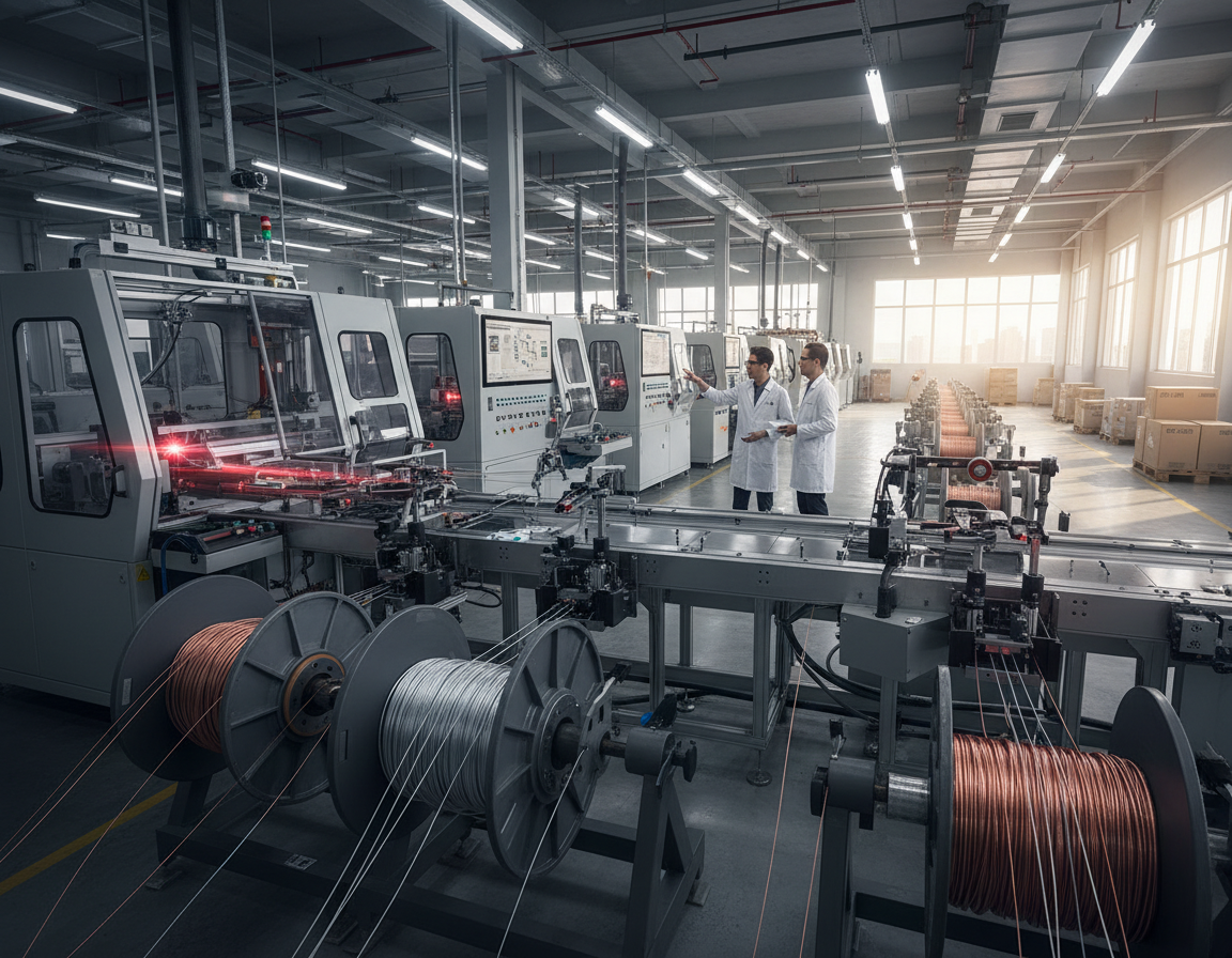
Is it feasible for a single fabrication process to offer complicated shapes, metal-equivalent tolerances, and compounds that resist heat all at once? Step inside this short guide regarding a scalable technology facilitating the creation of extremely precise, complicated ceramic parts. This method mixes microscopic powder with a binding agent to produce feedstock. That material is subsequently molded by injection, debound, and sintered to almost full density.

Learn more about bop inserts Houston

Major perks involve freedom of design, high repeatability, precise tolerances, and a surface finish matching metal techniques. It fits especially well when machining or tape casting fail at small, intricate parts.

Anticipate size variation from contraction during sintering; early DFM thinking lowers rework and cost.|Plan for dimensional changes caused by shrinkage in the sintering phase; strategic design-for-process decisions minimize cost and errors. The route supports medium-to-large production batches in which molds and processing speeds warrant the investment.

Applications span aerospace, automotive, healthcare equipment, electronics, and industrial components that require abrasion, heat, or chemical resistance.|Sectors include automotive, aerospace, medical devices, tech, and industrial parts requiring resistance to heat, wear, or corrosion. This guide guides the comprehensive journey from choosing materials through QA and highlights simulation and metrology tools to secure reliable results.

Understanding Ceramic Injection Molding And Its Relevance Now

The process of injection molding for micro-powder components employs a plastic or wax binder blended with powder to form a moldable feedstock.|Employing a wax or thermoplastic binder combined with powder, the injection molding method for powdered parts forms a flowable feedstock. This feedstock flows into complex cavities, yielding green parts with details difficult to replicate via dry pressing, slip casting, or isostatic pressing.

Comparison With Standard Methods

Unlike liquid or pressing techniques, this route allows for internal channels, undercuts, and thin walls in small-to-medium parts.|Unlike powder compaction or slurry methods, this path enables thin walls, undercuts, and internal channels within small-to-medium components. Production speed is greater and variability is reduced than hand-operated processes.|Output is higher, and variance is lower compared to manual methods.

Integration Into Modern Manufacturing

Typical flow: design for shrinkage → tooling → molding → debinding → firing → finishing.|The usual sequence: design for shrinkage → tooling → molding → debinding → sintering → finishing. Cycle times often range from seconds to a few minutes per shot.|Shot times generally run from seconds to minutes. Volume ideal ranges are mid-to-high runs in which the mold cost is amortized.

“Validating designs via Design of Experiments and test batches mitigates risk prior to full production.”

Method Geometry Speed Labor
CIM/MIM route High (undercuts, channels) High Minimal (can be automated)
Slip casting Moderate Low Intensive
Isostatic/dry pressing Simple to moderate Medium Medium

Post-process, polishing or laser machining can refine dimensions following sintering.|After sintering, laser features or lapping can improve tolerances. The process aligns well with statistical process control and production part approval protocols, improving traceability and manufacturing control. The obvious benefits nowadays are speed, lower waste, and the ability to enable designs otherwise prohibitively expensive.

Key Principles Behind Ceramic Injection Molding

This section explains the sequential route that converts fine powder and binder into a dimensionally stable part ready for sintering.|Here, we outline the step-by-step route converting fine powder and binder into a dimensionally stable part ready for sintering.

Transforming Powder And Binder Into Finished Parts

Begin by selecting ceramic powder with the correct particle size distribution and surface characteristics.|Start with selecting powder with the right surface area and particle size distribution. These traits govern viscosity, packing density, and the final microstructure.

  • Mix the powder with a tailored binder system and compound into raw material with target solids loading (usually 55–65 volume percent).
  • Use molding to form a green body; focus on gating to avoid weld lines and inconsistent density.
  • Remove binder to yield a fragile brown body, subsequently sinter to near-theoretical density.

Binders need to flow for good filling, maintain geometry while processing, and leave cleanly during binder removal to avoid bubbling or cracks.|Binders must flow to fill well, hold shape during handling, and exit cleanly during debinding to prevent cracks or blisters.

Feedstock rheology — thickness vs. temperature and shear — governs fill behavior, knit lines, and surface finish.|Feedstock rheology — viscosity against shear and temperature — governs fill behavior, surface finish, and knit lines. CIM machine design and screw configuration ensure material homogeneity and stop breakdown.|Machine geometry and screw/barrel design in CIM protect feedstock homogeneity and prevent degradation.
cast inserts Houston

“Manage the processing window: small variations in temperature or force frequently cause incomplete fills, air pockets, or bad surface quality.”

In comparison to MIM, this route uses higher sintering temperatures and different atmospheres to suit material chemistry and density needs.|Compared to MIM, this route uses different atmospheres and higher sintering temperatures to match densification needs and ceramic chemistry.

Preparing Materials And Feedstock For Precise Ceramics

Selecting the correct ceramic powders and binders lays the groundwork for consistent, accurate components.|The foundation for predictable, high-precision parts is set by selecting the right binders and powders.

Choosing Powders And Key Specs

Alumina is ideal when durability and dielectric strength are required.|Alumina excels where electrical insulation and wear resistance matter. Zirconium oxide provides fracture toughness for shock-prone components.|Zirconia adds fracture toughness for parts prone to shock. Silicon carbide suits extreme heat and harsh environments.|Silicon carbide suits abrasive and high-temperature environments.

Manage particle size, shape, and cleanliness.|Control purity, shape, and particle size. Fine, spherical powder enhances density and surface finish.|Spherical, fine powder improves surface finish and packing. Irregular particles can boost green strength but might roughen the finished surface.|Irregular particles can boost green strength but may roughen the final surface.

Binder Systems And Ratios

Typical binder families include waxes and plastics such as PE and PP, along with additives for difficult geometries.|Common binder families include polyolefins such as polypropylene and polyethylene, waxes, plus specialty polymers for difficult shapes. Binder content affects melt flow and removal speed.|Debinding time and melt flow are affected by binder percent.

Mixing And Flow Properties

Compound with a consistent sequence: dry mixing, slow polymer addition, then regulated heat and shear.|Compound using a steady sequence: dry powder blending, gradual polymer addition, then controlled shear and temperature. Avoid binder degradation by limiting peak temperatures.|Limit peak temperatures to prevent binder degradation.

Test material with rheometers or torque rheometers to verify flow ranges for consistent fill and compaction.|Test feedstock using torque rheometers or capillary rheometry to confirm viscosity windows for reliable packing and fill. Target solids loading that balances density and shrinkage — typically around 55–65 volume % for dense components.|Aim for solids loading balancing shrinkage and density — typically around 55–65 vol% for high-density parts.

Storage, Handling, And Drying

Store powders in airtight containers and use First-In-First-Out.|Store powders in sealed containers and use FIFO. Control humidity for hygroscopic additives and dehumidify feedstock before injection to minimize voids and defects.|Dry pellets before molding and control humidity for hygroscopic additives to reduce blemishes and voids.

Follow PPE and dust controls while working with fine powder and molten binders.|When handling hot polymers and fine powder, follow dust controls and PPE. Early vendor partnership on powder and binder choices speeds validation and lowers rework.|Early supplier collaboration on binder and powder choices lowers iteration risk and speeds validation.

Designing Parts For Injection Molding

Designing for this route starts with clear goals: achieve specs and reduce post-sinter work.|Designing for this route starts with clear goals: meet tolerances and limit post-sinter work. Early design choices influence shrinkage, strength, and manipulation of delicate green parts.|Early CAD decisions control shrinkage, strength, and handling of fragile green components.

Thickness, Gating, And Knit Line Control

Keep wall sections consistent and use gradual transitions to reduce sink and warpage.|Keep wall thickness uniform and use gradual transitions to reduce sink and warpage. Place gates such that flow flows from cosmetic or high-stress zones to avoid knit lines in critical zones.|Place gates so flow moves away from high-stress or cosmetic areas to avoid knit lines in critical zones.

Add a shrink map and resize dimensions in the mold to hit final dimensions.|Add a shrink map and scale key features in the mold to hit final dimensions. Verify with flow simulation and a DFM review prior to mold making.|Validate with flow simulation and a DFM review before tooling.

Features For Debinding/Sintering, Draft, And Radii

Provide slight draft angles and ample curves to ease demold and lower stress concentrations.|Provide modest draft angles and generous radii to ease demold and lower stress concentrations. Integrate gas vents, flow runners, or supports to speed debinding and hold fragile shapes.|Integrate vents, sacrificial channels, or setters to speed debinding and support fragile shapes.

Define datums and inspection points that match the way parts are held in firing and inspection.|Define datums and inspection points that match how components are fixtured during sintering and QC. Allow slight machining allowance for tight tolerances while avoiding too much material that raises cost.|Allow minimal finishing stock for critical fits while avoiding excess that raises cost.

Focus Area Recommendation Advantage Validation
Wall thickness Consistent, smooth changes Less warp; predictable shrinkage Simulation / prototype
Gating location Away from visual/stress areas Reduced knit lines Flow sim
Debinding features Vents, channels, setters Safer brown parts; fewer cracks DFM review

Mold And Tooling Factors For Ceramic Injection

An engineered toolset reduces scrap and enhances dimensional control across long production runs.|A well-designed toolset reduces scrap and improves dimensional control across long production runs. Start with material choices and coatings to handle abrasive feedstock and tight tolerances.|Start with material choices and surface engineering to handle abrasive feedstock and tight tolerances.

Tool steels should withstand wear and thermal cycling.|Mold materials should resist abrasion and thermal cycling. Select high-performance steels or superalloys and add wear-resistant coatings for extended tool life.|Select high-performance steels or nickel-based alloys and add wear-resistant coatings for extended tool life.

Optimize surface finish to aid release whilst preserving features.|Balance surface finish to aid release while preserving detail. Avoid textures that catch material or cause sticking.|Avoid textures that trap binder or cause sticking. Design venting to exhaust gas and volatiles and prevent dieseling or short shots.|Engineer venting to clear air and volatiles and prevent burn marks or short shots.

  • Select gating styles (side, submarine, hot tip) and runner layouts to ensure balanced filling and minimize weld lines.
  • Optimize cooling circuits to stabilize cavity temperature and reduce process drift.
  • Use strong ejection—stripper plates or air assist—to protect delicate molded parts upon demold.
  • Install swappable components for fast changes on inlets, vents, and critical dimensions.
  • Plan for variance by compensating cavities for expected shrinkage.
  • Embed internal pressure and thermocouples to track the process and enable closed-loop control.
  • Plan service cycles and wear checks to keep performance stable throughout production.

These steps tighten dimensional control and reduce downstream rework.|These measures tighten dimensional control and reduce downstream rework. They also support scalable production using advanced molding while protecting mold assets.|They also support scalable production using modern molding technology while protecting tool investment.

Step-by-Step: Running The Injection Molding Stage

A consistent molding cycle depends on temperature maps, pressure curves, and operator discipline.|A repeatable press cycle depends on temperature maps, pressure ramps, and operator discipline. Begin with a clear start-up checklist that safeguards feedstock and machine from thermal shock.|Start with a clear start-up checklist that protects feedstock and machine from thermal shock.

Machine Configuration: Speed, Pressure, And Temperature

Program cylinder and mold temperature profiles to keep viscosity stable without degrading the polymer.|Set barrel and mold temperature profiles to keep viscosity stable without degrading the binder. Adjust injection speed and pressure ramps to pack complex features while avoiding splaying and flow lines.|Dial in injection speed and pressure ramps to fill complex features while avoiding jetting and flow lines.

Packing, Cooling, And Filling For Precision Tolerances

Employ multi-stage packing to compact parts and eliminate internal voids.|Use multi-stage packing to densify green parts and reduce internal voids. Optimize chill time for handling strength and speed.|Balance cooling time for handling strength and cycle efficiency. Use purging and cleaning procedures to avoid mixing.|Implement purging and material changeover steps to avoid cross-contamination.

Ejecting Green Parts Without Damage

Use low-friction coatings and measured release agents as necessary.|Apply low-friction coatings and measured mold release where needed. Utilize gentle ejection and soft handling for delicate features.|Use controlled ejection and guarded fixtures for delicate features. Train operators to identify defects quickly and halt the run if required.|Train operators to spot defects early and stop the run if needed.

Control Goal Outcome
Barrel / mold temp Stable viscosity window Less short shots; good finish
Pressure & speed ramps Programmed multi-stage Full fill; fewer knit lines
Hold & Cool Multi-stage; balanced time Uniform density; dimensional stability

Debinding Methods And Best Practices

Successful binder removal is a vital step that converts a delicate molded part into a furnace-ready component.|Effective binder removal is a critical step that turns a fragile green part into a sinter-ready component.

Two main debinding methods are standard: solvent debinding and thermal debinding.|Two main debinding methods are common: solvent debinding and thermal debinding. Solvent debinding extracts the soluble components initially.|Solvent debinding extracts the soluble binder fraction first. Heat removal subsequently removes the residual polymer by controlled pyrolysis.|Thermal debinding then removes the remaining polymer by controlled pyrolysis.

Solvent Versus Thermal Approaches

Solvent processing is fast for dissolvable parts and lowers internal pressure in the next stage.|Solvent debinding is fast for soluble phases and reduces internal pressure during the next stage. Thermal processing is slower but necessary to remove hard-to-dissolve polymer.|Thermal debinding is slower but needed to remove hard-to-dissolve polymer. Selecting the correct approach depends on binder type and part shape.|Choosing the right method depends on binder chemistry and part geometry.

Avoiding Defects During Debinding

Support selection and positioning matter.|Fixture choice and part orientation matter. Brace fragile areas and allow free escape paths for gases to avoid cracking and warping.|Support fragile areas and allow free escape paths for volatiles to prevent cracking and distortion.

Use slow heat-up rates, dwells, and controlled airflow to prevent pressure spikes that lead to blistering.|Use gentle heating ramps, staged hold times, and controlled airflow to avoid pressure spikes that cause blistering. Thick sections and deep pockets require longer cycles or venting.|Thick sections and blind holes need longer cycles or local vents.

Select chemicals with recycling units and extraction.|Pick solvents with recovery systems and proper ventilation. Follow safety sheets and local environmental rules to protect staff and meet regulations.|Follow MSDS guidance and local environmental rules to protect workers and comply with regulations.

  • Test test coupons and sacrificial parts to verify complete debinding before firing.
  • Watch for odor, color change, or abnormal mass loss profiles—these indicate leftover binder.
  • Fix skinning, layer separation, or sagging by reducing heat rates, venting better, or changing supports.

Debinding success depends on molding and part quality; bubbles or knit lines frequently become cracks during debinding.|Debinding success ties back to molding and injection quality; voids or knit lines often become failure points during removal. Log profiles and weight data to normalize production and protect final part quality.|Record debinding curves and mass loss data to standardize processing and protect final part quality.

Sintering For Performance And Final Density

Precision sintering is the step that transforms a fragile brown shape into a dense, service-ready component.|Controlled sintering is the step that converts a fragile brown shape into a dense, service-ready part. The furnace cycle sets microstructure, density, and strength that dictate long-term performance.

Controlling Shrinkage, Atmospheres, And Temperature

Use a three-stage profile: gentle heating to remove residual binder, a controlled ramp to the densification range, and a controlled cooling to avoid thermal shock.|Use a three-stage profile: slow heat-up to remove residual binder, a controlled ramp into the densification range, and a measured cool-down to avoid thermal shock.

Align gas to chemistry: air for oxides, inert or hydrogen for non-oxides and some blends.|Match atmosphere to material: air for alumina-type oxides, inert or reducing for carbides and some engineered mixes. The correct atmosphere preserves composition and appearance whilst preventing grain boundary reactions.

Track contraction with test bars and feed data into mold scaling.|Measure shrinkage with sacrificial coupons and incorporate those values into cavity compensation. Design setters and fixtures to prevent distortion and allow uniform gas flow.|Design setters and supports to restrain warpage and allow uniform gas flow.

Optimizing For Strength, Wear, And Corrosion

Firing changes grain size and porosity, that control flexural strength and fracture toughness.|Sintering alters grain size and porosity, which drive flexural strength and fracture toughness. Target full density with low grain growth to achieve specs.|Aim for high density with minimal grain coarsening to meet mechanical targets.

Choose material chemistry and sinter soak times to maximize corrosion resistance and hardness for durability.|Select material chemistry and sinter soak times to optimize corrosion resistance and surface hardness for wear resistance. Evaluate HIPing if micro-pores impacts life or hermeticity.|Consider post-sinter HIP where residual porosity affects fatigue or sealing.

  • Record recipes and use sensors or optical sensing to validate heat accuracy.
  • Manage loading and gaps to ensure even heat and atmosphere exposure.
  • Watch for flaws: slumping, large grains, and trapped porosity—slow ramps and better support frequently resolve these.
Parameter Target Impact on Properties Tip
Ramp rate 1–5 °C/min (debinding) / 5–20 °C/min (sinter) Less cracks; grain control Match to binder and part mass
Soak temperature & time Material-specific peak; minutes–hours Density increase; porosity closure Use samples to verify
Atmosphere Air / N2 / H2 Preserves chemistry; prevents oxidation Flow meters and gas purity checks
After-treatment HIP/Annealing Remove pores; increase strength Apply when parts need max performance

“Consistent sintering recipes and calibrated ovens immediately increase output and cut finishing rework.”

QC, Measurements, And Tolerances

A robust metrology plan turns uncertainty in shrinkage into reliable specs.|A robust metrology plan turns uncertainty in shrinkage into predictable tolerances. Start with defined checkpoints at green, brown, and sintered states to catch errors sooner.|Start with clear inspection gates at green, brown, and sintered states to catch deviations early.

Mold Compensation And Shrinkage Measurement

Use shrink data from pilot runs to adjust mold sizes.|Use shrinkage correlation charts from pilot runs to scale cavity dimensions. Validate with sacrificial coupons and update the tooling offsets before production.|Validate with sacrificial coupons and update the mold compensation map before full tooling runs.

Checks For Porosity, Microstructure, And Surface Quality

Check surface finish and specific gravity with surface testers and density kits.|Inspect surface finish and density using profilometers and Archimedes testing. CT scans and optical scans reveal voids that affect strength.|Micro-CT and optical scans reveal internal pores that affect mechanical properties.

  • Establish inspection plans across green, brown, and sintered states with pass/fail gates.
  • Use tools: Coordinate Measuring Machines, vision systems, profilometers, micro-CT for internal checks.
  • Link microstructure and pore distribution with durability and wear performance.
Stage Instrument Metric Action
Green parts Optical scan Dimensions Tweak mold
Debound parts Micro-CT Internal flaws Adjust debind
Sintered parts CMM / profilometer Specs / Roughness Finalize process & release
Lot control SPC software Capability / Density Hold or release lots

Implement SPC and process studies prior to approval.|Implement SPC and capability studies before PPAP. Maintain traceability from batch-level raw materials to finished lots.|Maintain traceability from lot-level powders and binders through batches. Check tools, run MSA, and set reject procedures with corrective actions.|Calibrate gauges, run MSA, and define nonconformance flows with root-cause action plans.

“Accurate measurement and records close the loop on production quality.”

Applications And Industry Use Cases In The United States

Domestic producers prefer feedstock-based production when components must combine light weight and high wear resistance.|Domestic producers favor feedstock-based production when parts must combine low mass and high wear resistance. In aerospace, cars, medical, and tech, suppliers leverage this technology to meet tight specs and harsh environments.|Across aerospace, automotive, medical, and electronics, suppliers use this route to meet tight specs and harsh environments.

High Strength-To-Weight Components In Aerospace

For aviation, engineers specify lightweight bearings, jets, and heat shields that require efficiency.|In aerospace, manufacturers specify lightweight wear components, nozzle inserts, and thermal barrier parts that demand high strength-to-weight performance.

These parts improve MPG and withstand thermal shock and vibration in engines and controls.|These components improve fuel efficiency and survive temperature cycling and vibration in engines and actuation systems.

Thermal Stability And Durability In Automotive

Automotive use cases feature pump components, casings, and exhaust parts that need heat resistance and long-term durability.|Automotive use cases include pump components, sensor housings, and exhaust-related insulators that need thermal stability and long-term durability.

Swapping steel parts with ceramic parts reduces rust and extends lifespan in tough under-hood environments.|Swapping metal parts for engineered powdered parts reduces corrosion and extends service life in harsh under-hood environments.

Medical And Electronics: Miniaturization And Precision

Medical and electronics sectors benefit from tiny insulators, ferrules, implantable device components, and safe wear parts.|Medical and electronics markets benefit from micro-scale insulators, ferrules, implantable device components, and biocompatible wear parts.

These components require precision, insulation, and validated safety or dielectric testing before launch.|These components require tight tolerances, dielectric performance, and validated biocompatibility or dielectric testing prior to production release.

  • Performance edge: excellent hardness and chemical resistance render these parts ideal for harsh service.
  • Regulated production often adheres to aerospace standards, auto standards, or ISO 13485 with records and traceability.
  • Design-for-assembly matters for hybrid systems that join these ceramics to metals or polymers.
Stage Typical U.S. Lead Time Comment
Tooling to pilot 1.5 – 3 months Depends on insert complexity
Pilot to SOP 1 – 2 months Testing & Qual
Total 2.5 – 5 months Local supply helps speed

Validation steps involve bio-tests for implants and dielectric testing for devices.|Validation steps include biocompatibility studies for implants and dielectric testing for electronics. Many success stories demonstrate this method substituting metal parts to save weight and remove corrosion failure modes in the field.|Many success stories show this approach replacing metal designs to cut weight and remove corrosion failure modes in service.

Costs, Cycle Times, And When CIM Beats Machining

Understanding economics helps decide if CIM or CNC is the smarter path.|Understanding economics helps decide whether formed-powder production or machining is the smarter path. Begin by listing the key costs and the way cycle time impacts budget.|Start by mapping the main cost drivers and how cycle time affects cash flow.

Key Cost Drivers

Molds and tool amortization often are the biggest upfront cost.|Tooling and mold amortization often dominate initial spend. Hardened tools or swappable inserts raise initial investment but reduce unit cost at scale.|High-performance steels or interchangeable inserts raise up-front cost but lower per-piece cost over volume.

Raw material, press time, sintering time, manpower, and scrap all add to final cost.|Material/feedstock, press time, furnace soak, labor, and yield losses all add to true landed cost. Post-processing, inspection, and packaging also matter.|Secondary finishing, inspection, and packaging also matter.

Driver Impact Mitigation
Tooling / mold High up-front; lowers per-part at scale Inserts; high volume
Materials Variable cost; impact on yield Negotiate lots; optimize solids loading
Machine & furnace time Determines rate Match molding to sintering
Yield / rework Profit killer Design for uniform walls and gate locations

CIM Advantages Over Machining

In complex shapes and mid-to-high volumes, per-part costs are lower than machining.|For complex geometry and mid-to-high volumes, per-part costs fall below machining. Cutting brittle blanks generates waste and long cycle times for inner features.|Machining brittle blanks creates much scrap and long cycle times for internal channels.

Machining is better for prototypes, oversized pieces, or if tolerances need grinding.|Machining still wins for very low volumes, oversized pieces, or when tolerances need tight post-sinter finishing.

“Design optimization and batch planning turn fixed costs into competitive per-part pricing.”

Practical Quoting Heuristics

  • Estimate tooling payback: tooling cost ÷ expected units = tool cost per unit.
  • Sum feedstock, machine time, sinter cost, work, QA, and packaging to get unit cost.
  • Add a yield loss (5–15%) and a secondary finishing allowance.

This method outlines total cost of ownership and reveal where engineering, methods, and better molds deliver the biggest advantages.|These steps frame total cost of ownership and show where design, process choices, and smarter tooling deliver the biggest advantages.

Solving Common CIM Defects

Identifying the real cause of short shots or distortion needs a mix of data and structured problem-solving.|Finding the real cause of short shots or warpage needs both data and structured problem-solving. Use a basic checklist to distinguish issues that start in molding, debinding, or sintering.|Use a simple checklist to separate problems that start in molding, debinding, or sintering.

Typical Defects And Quick Diagnoses

Short shots and voids happen if injection speed or pack pressure is insufficient, vents are clogged, or feedstock contains water.|Short shots and voids happen when injection speed or pressure is too low, vents are blocked, or feedstock carries moisture.

Distortion frequently traces to unequal packing, nonuniform cooling, or poor support in sintering.|Warpage often traces to unequal packing, nonuniform cooling, or poor support during sintering.

Separation and weak knit lines respond to gate redesign, hotter material, or flow balancing across cavities.|Delamination and weak knit lines respond to gate redesign, higher melt temps, or flow balancing across cavities.

  • Debinding blistering/cracks: slow heating, thick walls, or bad solvent flow.
  • Check mold wear and scratches when flaws start following high volume.
  • Implement incoming inspection to control material changes and humidity.

“Apply structured root-cause tools such as Ishikawa and the Five Whys to find process errors.”

Defect Root Cause Fast Action
Short shot/void Low pressure/speed, poor venting Increase injection pressure; clear vents
Warp Uneven packing/cooling Balance fill; adjust cooling
Cracking Debinding ramp or solvent issue Slower heat; check solvent

Perform experiments to tune parameters and confirm fixes.|Run DOE to tune parameters and verify fixes. Monitor failure codes and charts to focus improvements.|Track defect codes and Pareto charts to focus improvements. Close the loop among press operators, furnace techs, and QA to shorten time-to-correct and improve yield in the plant.|Close the loop between press operators, furnace techs, and QA to shorten time-to-correct and raise overall quality in the process.

Compliance, Sustainability, And Safety

Safeguarding workers and the environment is just as critical as hitting tolerances in modern manufacturing.|Protecting workers and the environment is as important as hitting tolerances in modern powder-based production.

Handling Powders And Binders Safely

Wear gear: N95 or P100 respirators, gloves, eye protection, and protective clothing for powder and hot binder work.|Use PPE: N95 or P100 respirators, chemical-resistant gloves, eye protection, and protective clothing for dry powder and hot binder work.

Install local exhaust ventilation and HEPA filtration to control airborne powder.|Install local exhaust ventilation and HEPA filtration to control fugitive dust. Enclose hoppers and use grounded transfer lines to mitigate static risks.|Enclose transfer points and use grounded transfer lines to reduce static risks.

“Train staff on cleanup, binder hazards, and storage rules—practice simplify inspections.”

Energy, Recycling, And Waste Management

Segregate waste streams: loose powder, binder waste, chemicals, and general refuse.|Segregate waste streams: loose powder, used binder, solvent residues, and general refuse. Label containers and keep solvent and powder streams separate for recycling.|Label containers and keep solvent and powder streams separate for recovery.

Implement closed-loop solvent recovery and regrinding where quality permits.|Adopt closed-loop solvent recovery and controlled feedstock regrind where quality permits. Doing so reduces waste fees and preserves raw materials.|This reduces disposal costs and preserves raw materials.

Plan sinter batches to fill the kiln and reduce energy spikes.|Schedule furnace loads to maximize fill and minimize peak demand. Upgrade insulation, use high-efficiency motors and VFDs, and track power usage for standardized efficiency.|Improve insulation, use high-efficiency motors and variable-speed drives, and log energy data for ISO 14001-style continuous improvement.

Comply with safety and environmental regulations for pollutants, solvent emissions, and recordkeeping.|Follow OSHA and EPA rules for hazardous air pollutants, solvent emissions, and recordkeeping. Keep documented procedures, logs, and material safety data sheets available for audits.|Keep documented procedures, training records, and material safety data sheets ready for audits.

Design components to cut mass and processing time—these actions reduce power and offer clear environmental advantages while keeping manufacturing reliable.|Design parts to cut mass and cycle time—these simple choices lower energy use and offer clear environmental advantages while keeping production reliable.

Next Steps: Bringing Your Ceramic Injection Molding Project To Production

Convert concepts into reliable production by sequencing material trials, tool proofs, and pre-production.|Turn design intent into reliable production by sequencing material trials, tool proofs, and pilot runs.

Checklist: select material, do DFM, run simulation, make prototype tool, complete validation runs, then execute approval or equivalent.|Practical checklist: pick feedstock, run a DFM review, simulate flow, build a prototype mold, complete validation runs, then execute PPAP or equivalent.

Establish goals from Quote → prototype tool → capability studies → first article inspection → SOP.|Set milestones from RFQ → prototype tool → capability studies → first article inspection → SOP. Confirm requirements and timelines with suppliers to secure early choices.|Agree deliverables and timelines with suppliers to de-risk early choices.

Document quality plans, work instructions, and KPIs before launch.|Document control plans, work instructions, and quality metrics before pilot production. Prepare resources for press tonnage, furnace volume, debinding, and staffing.|Plan capacity for press tonnage, furnace volume, debind throughput, and staffing.

Aim for early wins where accuracy and complexity add value.|Target early wins where precision and complex geometry add value. Maintain quality with PM, calibration, and audits.|Maintain quality with preventive maintenance, gauge R&R, and periodic requalification.

Ready to proceed? Ask for a review and a quote using your parts, volumes, and requirements.|Ready to proceed? Request a feasibility review and a cost model based on your parts, volumes, and performance needs.

FAQ

itemprop=”name”>How are precision ceramic parts made with injection molding?

The method begins with mixing ceramic or carbide powder with a binder to create a homogenous feedstock.|The process starts by mixing fine oxide or carbide powder with a polymer-based binder to form a homogenous feedstock. That feedstock is shot into a mold under pressure to create a green body.|That feedstock is shot into a mold under pressure to create a green part. Post-molding, the polymer is extracted via debinding, and the part is fired to achieve final density and strength.|After molding, the binder is removed through solvent or thermal debinding, and the part is sintered to reach final density and mechanical properties. Every step — mixing, molding, washing, and firing — must be controlled to hit tight tolerances and quality goals.|Each stage — compounding, molding, debinding, and sintering — must be controlled to meet tight tolerances and material performance targets.

itemprop=”name”>What is the difference between CIM and slip casting or pressing?

In contrast to pressing or casting, that shape parts one at a time or need finishing, CIM enables mass production of complex shapes with fine features and repeatability.|Unlike pressing or slip casting, which shape parts one at a time or require significant machining, injection enables high-volume production of complex geometries with fine features and consistent repeatability. It also lowers post-sintering machining for many components, increasing material yield and lowering unit cost at scale.|It also reduces post-sintering machining for many components, improving material yield and lowering per-part cost at scale.

itemprop=”name”>What materials are used in ceramic injection molding?

Typical materials include aluminum oxide, zirconium oxide, and SiC.|Common powders include alumina, zirconia, and silicon carbide. Carbides appear when extreme wear resistance matters.|Tungsten carbide blends appear where extreme wear resistance matters. Material choice is based on required strength, thermal stability, chemical resistance, and electrical properties.|Powder selection depends on required strength, thermal stability, corrosion resistance, and electrical properties. Proper powder surface chemistry and particle size distribution influence feedstock flow and final density.|Proper powder surface chemistry and particle size distribution also affect feedstock flow and final density.

itemprop=”name”>Why are binders used and how to select them?

Binders offer cohesion and lubricity during molding, and must be removable avoiding damaging the part.|Binders provide cohesion and flow during molding, then must be removable without harming the part. Typical systems use waxes and plastics in set amounts to manage flow, green strength, and removal.|Typical systems use waxes and polymers in controlled ratios to balance viscosity, green strength, and debinding behavior. Choice depends on shape, removal process, and environmental or safety requirements.|Selection depends on part geometry, debinding method, and environmental or safety requirements.

itemprop=”name”>How do designers account for shrinkage and tight tolerances?

Engineers adjust by scaling mold cavities to counteract expected shrink during sintering.|Designers compensate by scaling mold cavities to offset predictable linear shrinkage during sintering. They also control walls, fillets, and locate gates to reduce welds and deformation.|They also control wall thicknesses, add radii, and locate gates to minimize knit lines and deformation. Close collaboration with the molder helps set realistic specs using material and process capability.|Close collaboration with the manufacturer helps set achievable tolerances based on material and process capability.

itemprop=”name”>How does the mold affect CIM part quality?

Tool steel, polish, air vents, and gate and runner design all influence fill, packing, and demolding.|Mold material, surface finish, venting, and gate and runner design all influence filling, packing, and demolding. Hardened steels with smooth surfaces lower flaws.|Hardened steels with polished cavities reduce surface defects. Good venting prevents trapped gas and short shots, while optimized gates produce smooth flow and limit weld lines.|Proper venting prevents trapped gas and short shots, while optimized gates yield consistent feedstock flow and reduce weld lines.

itemprop=”name”>Optimizing molding for precision dimensions?

Machine parameters — temps, speeds, and holding pressure — are adjusted to guarantee full fill and density.|Machine parameters — barrel and mold temperature, injection speed, and holding pressure — are tuned to ensure complete cavity fill and consistent packing. Cooling and ejection time are set to avoid warping of green parts while maintaining speed.|Cooling and demolding timing are set to avoid distortion of green parts while maintaining cycle efficiency. Monitoring process data assists to keep variation low.|Monitoring process data helps keep variation low.

itemprop=”name”>Debinding methods: Types and usage?

Solvent debinding extracts soluble parts and is gentle for details.|Solvent debinding extracts soluble binder fractions and is gentle for complex features. Heat debinding ramps temperature to burn off or pyrolyze the remainder and is often applied after solvent steps.|Thermal debinding ramps temperature to evaporate or pyrolyze the remainder and is often used after solvent steps. The decision depends on binder chemistry, wall size, and danger of cracking or blistering.|The choice depends on binder chemistry, part thickness, and risk of cracking or blistering.

itemprop=”name”>Avoiding cracks and blisters during debinding?

They control heating rates, ensure venting paths, and employ staged solvent/thermal sequences matched to feedstock.|They control heating rates, ensure venting paths, and use staged solvent/thermal sequences tailored to feedstock. Even removal and reducing gas build-up during decomposition reduce stresses that create cracks or blisters.|Uniform binder removal and minimizing internal pressure during decomposition reduce stresses that cause cracks or blisters.

itemprop=”name”>What sintering practices ensure final strength and wear or corrosion resistance?

Furnace cycles — temperature, hold time, ramp rates, and gas — are tuned for shrinkage whilst controlling coarsening.|Sintering profiles — temperature, hold time, ramp rates, and atmosphere — are optimized for densification while limiting grain growth. Controlled atmospheres or isostatic post-sinter densification are used to reach full density, toughness, and finishes such as durability.|Controlled atmospheres or isostatic post-sinter densification may be used to achieve target density, strength, and surface properties like wear and corrosion resistance.

itemprop=”name”>How is quality measured and guaranteed across production runs?

QC uses dimensional inspection adjusted for shrinkage, microstructure analysis, density checks, and mechanical testing.|Quality control uses dimensional inspection adjusted for shrinkage, microstructure analysis, porosity checks, and mechanical testing. SPC monitors key parameters to keep repeatability, and first-article inspection validates mold sizing and sintering outcomes.|Statistical process control monitors key parameters to maintain repeatability, and first-article inspection validates tooling compensation and sintering outcomes.

itemprop=”name”>Which industries in the United States most benefit from this manufacturing route?

Aerospace, auto, medical devices, and electronics are key users.|Aerospace, automotive, medical devices, and electronics benefit most. Common applications include wear parts, high-strength parts needing tight geometries, and micro parts where machining would be too expensive.|Typical uses include thermal or wear-resistant components, high-strength parts requiring tight geometries, and miniature parts where machining would be impractical or costly.

itemprop=”name”>CIM vs Machining: When is CIM cheaper?

It becomes economical when volumes rise, geometries are intricate, or combining parts reduces assembly.|It becomes economical when volumes rise, geometries are complex, or part consolidation reduces assembly steps. High tooling cost is spread over volume, and the reduced need for cutting decreases material waste and cycle cost per component.|High tooling cost is amortized over many parts, and the reduced need for machining lowers material waste and cycle cost per component.

itemprop=”name”>Diagnosing common CIM molding defects?

Short shots, holes, warpage, and delamination can stem from material issues, bad venting, incorrect process settings, or bad processing.|Short shots, voids, warpage, and delamination can stem from feedstock problems, poor mold venting, incorrect process settings, or improper debinding/sintering. Troubleshooting maps flaws to stage, and isolates variables like force, temperature, or flow for fixing.|Root-cause analysis maps defect location to process step, then isolates variables like pressure, temperature, or feedstock rheology for correction.

itemprop=”name”>Safety and environment in CIM processing?

Use local exhaust ventilation, dust controls, and appropriate PPE when handling particulates.|Use local exhaust ventilation, dust controls, and appropriate PPE when handling fine powders. Dispose of chemicals according to OSHA and EPA guidelines.|Manage solvent and binder waste per OSHA and EPA guidelines. Recycling of scrap feedstock and energy-efficient sintering reduce impact.|Recycling of scrap feedstock and energy-efficient sintering reduce environmental footprint.

itemprop=”name”>Starting a CIM production project?

Begin with material selection and a design review for manufacturability.|Start with material selection and a design review for manufacturability. Run samples to validate feedstock, tooling, and thermal profiles.|Produce pilot parts to validate feedstock, mold compensation, and thermal profiles. Refine tooling and process parameters, then scale with vendors who can show consistent metrology and control.|Iterate tooling and process parameters, then scale with qualified suppliers who can demonstrate consistent metrology and process control.

The Role of Precision Measurement Tools at AMT in Surgical Component Quality

AMT: Premier Endoscopic Surgery Component Manufacturer.

75% of minimally invasive surgeries depend on precision parts, embedded in scopes and tools for endoscopic procedures.

AMT, located in Singapore, specializes in medical device components, delivering high-quality parts for endoscopic surgical instruments. It emphasizes precision across flexible and rigid endoscopy platforms.

Clinicians and procurement groups turn to AMT for quality components, with AMT: endoscopic surgical component manufacturer work seen as essential during supplier selection. In this article, we summarize AMT’s offerings, quality focus, service model, and market coverage.

Meet AMT, Singapore’s leader in endoscopic surgical components—boosting minimally invasive surgery with accuracy and excellence.

AMT’s Role in Endoscopic Instrumentation

For hospitals, clinics, and surgical teams across Singapore and the region, AMT serves as a key partner, merging global technology with local support. The result is dependable quality and responsive support for front-line teams.

endoscopic surgical component manufacturer: AMT

Background and Mission

AMT grew from a regional distributor into a specialized maker and supplier of medical devices, with a mission to build lasting relationships through top-notch products and service. Training, warranty coverage, and fleet management underscore AMT’s commitment to long-term value for providers.

Product Focus: Flexible & Rigid Endoscopy Components

AMT’s portfolio centers on flexible endoscopy components in gastroenterology, bronchoscopy, and EUS/EBUS—including imaging systems, light sources, accessory channels, and single-use items. Its range also covers rigid endoscopy and MIS tools for diagnosis and therapy.

AMT’s positioning among medical device manufacturers in Singapore and the region

AMT serves Singapore and export markets, delivering cutting-edge tech to Southeast Asia and beyond. It operates as a surgical device supplier with timely local service and global procurement readiness.

End User Key Requirements How AMT Addresses Needs
Physicians Consistent imaging, dependable instruments Clinically validated imaging modules and instrument components
Reprocessing Staff Safe disposables, clear IFUs Provides consumables, reprocessing aids, and technical guidance
Biomed Teams Fast repairs, assured spares OEM-level repairs, loaner pools, fleet programs
Procurement & Hospital Buyers Cost-effective sourcing and supplier reliability Transparent pricing, training, documented QA

AMT – Endoscopic Surgical Component Manufacturer

Clarity speeds procurement: positioning AMT as an endoscopic surgical component manufacturer directs buyers to endoscopy-ready solutions. Singapore teams prefer suppliers who state offerings plainly.

Why Positioning Matters for Procurement

Being specific streamlines sourcing—buyers of GI scopes shortlist vendors with endoscopy credentials. It matches technical, documentation, and compliance needs, reducing risk.

Clinicians/Buyers: Finding the Right Suppliers

Clinicians seek suppliers who understand their domain; this tag signals AMT’s fit for lungs, bladder, and women’s health.

Buyers find endoscopy-centric suppliers with parts, loaner programs, and training—superior to broad, unfocused catalogs.

Implications for regulatory, quality and supplier selection

Robust regulatory/quality frameworks are vital; buyers need full documentation and controls.

Capable service teams are equally important—repair times and rapid support keep devices ready.

Criterion What Buyers Should Verify Rationale
Product Registration SG registrations and labeling Legal supply, audit speed
Quality Systems ISO, traceability, batch docs Consistency and safety
Parts Sourcing Genuine vs alt parts, availability Affects longevity, warranty, repair outcomes
Service Trained techs, onsite help, loaners Less downtime, on-time cases
Documentation Manuals, service logs, reprocessing guidance Enables biomed workflows and compliance

Key AMT Endoscopic Components

AMT supplies essential endoscopy tools for hospitals and outpatient centers in Singapore, pairing superior optics, advanced imaging electronics, and procedure-ready disposables.

Imaging & Visualization

Across GI, urology, and gynae, AMT provides rigid/flexible optics with camera heads and LED lights to deliver crisp, high-contrast views.

IT-friendly capture/archiving integrates with endoscopy software, boosting records, cycle time, and utilization.

Procedure Accessories and Disposables

With biopsy forceps, insufflation tubing, and more, AMT’s branded disposables help avoid stockouts and ease purchasing.

Compatibility with standard platforms accelerates room turnover and keeps schedules on track.

Instruments for Minimally Invasive Surgery

AMT covers laparoscopy and electrosurgery across specialties, with reusable and disposable options to balance cost and infection control.

Procedure bundles package instruments and disposables to streamline efficiency and minimize delays.

Therapeutic and diagnostic additions—like reflux assessment devices—round out endoscopy suites and outpatient rooms.

Quality assurance and service: OEM-level repair and technical support

Comprehensive QA plus accessible service—factory-trained staff (GTA center) and proactive site visits—help prevent issues and train users.

Factory-Trained Techs & Onsite Advantages

OEM-trained techs repair and calibrate per spec; on-site work cuts wait times and reduces downtime, keeping devices ready and within maker standards.

Loaner Pools and Rapid Estimates

Loaners maintain operations while equipment is serviced; rapid estimates support budgets and avoid case cancellations.

Balanced Approach: Non-OEM Labor, OEM Spares

Non-OEM labor plus OEM spares manages cost yet preserves traceability/performance for audit-ready outcomes.

Fleet programs add maintenance, user training, and records, extending lifespan, ensuring safety, and improving availability for Singapore hospitals.

Clinical applications and specialties served

Customized endoscopic offerings support diagnosis, treatment, and daily workflows for teams in Singapore and the region.

Gastroenterology and flexible endoscopy components

Flexible scopes and imaging gear suit high-throughput GI units, plus EUS and therapies like polypectomy and hemostasis.

Reflux and motility diagnostics alongside single-use items simplify complex GI procedures.

Pulmonology & Bronchoscopy

Airway care uses flexible bronchoscopes and sampling tools for routine to advanced interventions.

Visualization plus tool access supports biopsy and airway stenting.

Urology, gynecology and general surgery use cases

Urology gets cystoscopes and stone tools; gynae receives instruments for operative hysteroscopy and minimally invasive care.

General surgeons use durable, interoperable tools compatible with energy systems and modern techniques.

Close collaboration with infection control, nursing, and biomed ensures device fit, reduces delays, and enhances safety.

Specialty Key components Typical Use
Gastroenterology Flexible scopes, EUS probes, biopsy forceps Diagnostics, polyp removal, EUS therapy
Airway Flexible bronchoscopes, visualization modules, suction catheters Inspection, BAL, biopsy
Uro Cystoscopy tools, laser adapters, baskets Stone management, tumor assessment, diagnostics
Gynecology Hysteroscopes, distension, operative tools Diagnostic hysteroscopy, polyp removal, adhesiolysis
General Surgery (MIS) Scopes, trocars, energy accessories MIS, energy cases, suturing

Regulatory & Reprocessing

Singapore hospitals need clear cleaning and safety directions; AMT aligns products and documents to meet these standards.

HLD & Storage Requirements

High-level disinfection prevents device-related infections; AMT provides accessories compatible with AERs and manual workflows.

Proper drying and storage reduce cross-contamination between cases; AMT designs parts that support safe handling in CSSD/sterile services.

Reprocessing & Biomed Collaboration

Working with reprocessing and biomed, AMT confirms cycles, chemistries, and interfaces.

Biomed teams rely on documentation and service info to update maintenance plans.

How AMT supports infection prevention and control practitioners

Training, manuals, and records help IPC efforts; clear labels and logs stay audit-ready.

Spare parts and rapid assistance resolve reprocessing issues quickly, sustaining prevention efforts.

Technology partnerships and supply chain strategy

AMT builds ties with leading device makers to deliver modern imaging, therapy tools, and accessories—opening OEM parts and authorized service for longer product availability and higher repair quality.

Global OEM Relationships

With partners such as Olympus, Stryker, and Pentax Medical, AMT secures products/training that enable validated components and certified support.

Export & Market Presence

Singapore anchors regulatory and distribution; export playbooks—akin to Canada—ensure smooth customs and post-sale backing.

Stakeholder engagement and business intelligence for healthcare procurement

Regular surgeon/nurse/biomed engagement informs needs and prevents supply issues, clarifying IPC priorities and purchasing decisions.

Area Practical Benefit How AMT Delivers
Technology partnerships Faster access to new imaging and therapeutic parts Authorized agreements and factory-trained technicians
Supply chain resilience Lower downtime and reliable spares Dual-sourcing, regional inventory, prioritized logistics
Market access Simplified procurement across jurisdictions Regulatory support from Singapore hub, export-ready docs
BI Data-driven purchasing and risk forecasting Market analysis and stakeholder feedback loops
Engagement Better alignment with clinical workflows Visits, training, briefings

AMT’s alliances plus smart market access and BI support stable supply, certified repairs, and informed purchasing—offering clinical teams steady inventory and fast fixes.

Where Surgical Tech Is Heading

AMT operates where new ideas meet daily clinical needs; demands for better images and precise energy delivery shape the roadmap.

Imaging & Energy Trends

Advances in cameras, optics, and small processors set benchmarks—clearer views, faster updates, and low latency.

Safety/predictability in energy systems demands tight integration with imaging and processors to lower surgical risks.

Informatics & Workflow

Data-connected capture, archiving, and analytics boost documentation and throughput for endoscopy units.

Vendors who deliver intuitive software and training smooth digital transitions for clinical, technical, and IT teams.

Growth Opportunities

Growth avenues include MIS-imaging-energy bundles plus service contracts and data offerings to stabilize spend.

Deep OEM collaboration (e.g., Olympus, Stryker, Karl Storz) accelerates access, while regional stock keeps availability.

Supplier Selection Checklist for Hospitals

Selecting the right supplier impacts operations, budgets, and patient safety; assess product breadth, service speed, technical depth, transparent costs, and lifecycle support.

Range, Speed, and Loaner Pools

Confirm broad coverage across imaging, accessories, and MIS instruments to reduce multi-vendor complexity and ensure compatibility; verify after-hours support.

Ask about loaner devices to avoid cancellations; rapid replacements indicate readiness and reliability.

Skills, Preventative Maintenance, Education

Hands-on, engineer-led training cuts errors and prolongs device life.

Ensure scheduled preventative maintenance with comprehensive guides to reduce breakdowns and keep devices ready.

Cost transparency, quick repair estimates and lifecycle support

Insist on transparent parts/labor pricing and same-day quotes to aid budgeting and scheduling.

Confirm spare parts access and non-OEM repair options with clear SLAs to manage total lifecycle cost.

Checklist for Procurement

  • Registration and local regulatory compliance status
  • Service capabilities and tech credentials
  • Loaner equipment inventory and turnaround times
  • Reprocessing compatibility and technical documentation
  • Policy for quick estimates and transparent billing

Real-World Value: Downtime Reduction

Singapore hospital examples show how rapid service and fleet programs save money and time; small process changes reduce delays and keep schedules.

Repair Speed and Fleet Wins

A public hospital improved repair turnaround by 40% via local service and routine checks, lowering waits and preventing cancellations.

How access to loaner equipment supports continuous clinical operations

Loaner programs kept a major center running during failures; usage analytics guided cost-cutting moves.

Value From Non-OEM Service

Using OEM spares in non-OEM service reined in costs and kept reliability, with blended strategies yielding better TCO.

Monitor turnaround, loaner use, reliability, and repair cost; target metrics drive savings and fewer delays.

Endoscopic Market Outlook in SG & SEA

Growing volumes and service lines push endoscopic demand; aging cohorts and MIS trends increase needs in GI, pulmonary, and general surgery.

Demand Drivers & Adoption

Clinicians favor less invasive procedures for faster recovery and lower infection risk, prompting investments in scopes and imaging.

High procedural volumes at public and private centers require dependable supply and quick service.

Regulatory and procurement trends

Traceable, validated cleaning pushes buyers toward locally supportive suppliers.

Loaner programs and fast quotes are increasingly preferred.

Competitive landscape and market players

Global brands, regional distributors, and specialized service firms compete; cost-effective repair offerings can differentiate.

Using market data and forums helps forecast risk and spot growth opportunities for supply chains.

Factor Procurement Impact Supplier Response
MIS Adoption Raised demand for scopes/cameras/MIS Wide product range and clinical training
Aging Demographics Increased GI/pulmonary volumes Consistent supply, predictable lead times
Regulatory scrutiny Tighter docs and reprocessing rules Traceable records, validated protocols
Procurement trends Preference for local support and fast service Loaners, rapid quotes, onsite techs
Competitive landscape Service differentiation across players Quality proofs, regional presence, transparent costs

In Closing

As an endoscopic surgical component manufacturer, AMT provides quality parts, OEM-grade service, loaner support, and rapid estimates to reduce clinical downtime in Singapore.

Its work underpins specialties like gastroenterology and general surgery, ensuring safety and compliance through close collaboration with hospital teams.

AMT aims to grow by improving products and expanding regional presence; hospitals should weigh product breadth, service speed, regulatory backing, and lifecycle cost to keep surgery services smooth and safe.

Nep Denim Coasters: Craft Project Guide

Mastering Selvedge Denim Material: A Full Guide

A lone pair of classic Levi’s 501s dating back to the 1940s commanded $87,400 under the hammer at auction. What caused these jeans to outprice a luxury vehicle? It’s all due to their selvedge denim build.

This high-end denim stands for more than simple material. It recalls the era when James Dean donned his 501s in Rebel Without a Cause, and Marlon Brando epitomized cool in The Wild One. Those pop culture legends weren’t merely clad in denim. They sported Nep denim made on historic shuttle looms.

Handcrafted denim earns its moniker from the self-finished borders that stop fraying. The term “selvedge” combines “self” and “edge” to describe this unique weaving method. In contrast to mass-made denim, every yard of selvedge denim material demands time and craftsmanship.

The texture tells a story through subtle irregularities and natural variations. Each pair develops its own character as the indigo fades. This individual progression renders heritage denim exceptional to collectors and style aficionados alike.

Numerous people assume high-end denim endures beyond ordinary jeans. The reality, however, is more delicate. Selvedge crafting produces lovely material with tidy edges and robust texture. However, sturdiness relies on cotton caliber and heft, not merely on weaving style. What differentiates artisanal denim is its knack for aging with grace and creating singular fading designs in the long run.

What Is Selvedge Denim Material

Selvedge denim cloth stands apart from standard denim because of its special build and polished borders. It’s titled after its “self-edge,” a closely woven strip that blocks fraying. This top-tier fabric embodies a commitment to slow fashion and classic artisanry, distinguishing it from factory-produced denim.

black selvedge denim fabric

Decoding Self-Edge Construction

The term “selvedge” is a blend of “self” and “edge,” describing fabric with a clean, finished border. This narrow selvage appears on both sides of the fabric, doing away with extra finishing. Heritage mills make it about 30–32 inches wide, as opposed to modern denim’s 60-inch breadth.

How Shuttle Looms Create Unique Fabric Edges

Denim from shuttle looms derives its persona from antique weaving machines running at reduced speeds. They pass one weft yarn across all warp threads in a single sweep. This process yields:

  • Natural irregular slubs
  • A gentler hand-feel compared to contemporary denim
  • Securely finished edges that resist fraying
  • Authentic irregularities cherished by denim enthusiasts

How Selvedge Differs from Standard Denim

Regular denim comes from projectile looms firing weft yarns over broader widths. Such weaving leaves loose edge fibers requiring overlock stitching to stop fraying. Selvedge denim fabric, however, requires extra time in production. It provides greater longevity and a special style, meriting its loftier price tag.

Heritage and Historical Roots of Shuttle-Loomed Denim

The journey of heritage denim started in American textile mills in the 1800s. Shuttle looms were central, weaving material with sealed edges to avoid fraying. This method produced indigo-dyed denim at a slow, meticulous pace, ensuring each yard was crafted with care. Its slender width evolved into a trademark of artisan denim manufacture.

American Mills of the 1800s to Today’s Resurgence

For upwards of a century, American factories leaned on shuttle looms. Names such as Cone Mills and White Oak furnished top denim to workwear makers. By the 1970s, faster projectile looms took over, replacing most shuttle equipment. This shift was driven by the need for cheaper, mass-produced jeans. Many historic mills closed or modernized, leaving vintage looms to gather dust.

The Rise of Japanese Selvedge Excellence

In the 1980s, Japanese producers brought American shuttle looms back into use. The Osaka Five labels headed this resurgence:

  • Studio D’Artisan
  • Evisu
  • Fullcount
  • Warehouse
  • Denime

Those firms blended U.S. retro flair with Japanese exactness. They researched antique Levi’s templates, reproducing classic indigo denim textures. By 2000, Japanese makers had overtaken the global artisan denim market.

The Importance of Traditional Weaving Today

Shuttle looms yield distinct cloth traits that contemporary machines cannot replicate. The slower weaving process allows for irregular textures and deeper indigo penetration. Hardcore denim fans treasure these quirks as proof of real craftsmanship.

Shuttle Loom Features Modern Loom Features
29-31 inch fabric width 60+ inch fabric width
3-4 yards per hour 15-20 yards per hour
Natural irregularities Uniform texture
Self-finished edges Cut edges requiring overlocking

Making Premium Denim on Antique Looms

Premium denim production kicks off with the steady rhythm of antique shuttle looms. These machines differ from today’s technology. They weave yarn across the fabric width in a single thread, locking the edges without finishing. This technique assures a crisp, fray-resistant edge on selvedge denim.

Vintage looms weave at a slower pace, producing just 5-6 meters of slub denim daily. This sharply contrasts with current machines that manage 200 meters. The unhurried pace advantages the yarn via:

  • Reduced fiber tension yields a gentler feel
  • Organic irregularities stay put, granting unique texture
  • Varied surfaces produce signature fading
  • Slim widths (around 29–32 inches) cut down waste

Manning these age-old looms calls for seasoned artisans. Operators fine-tune tension, track cadence, and carry out maintenance. Every loom boasts its own personality. Many were built in the 1920s and require know-how passed through the ages. This tactile method turns shuttle-loomed denim into an authentic artisan good.

The slim width of dry denim on antique looms offers a real advantage. Denim craftsmen can employ the finished edge as the outseam, cutting waste. This showcases the fabric’s authentic construction. Every roll has its own story, with subtle variations that mass production can’t replicate.

Understanding Raw Denim vs Selvedge Differences

A lot of denim fans mix up raw denim and selvedge denim. This misunderstanding crops up while seeking high-end jeans. The fact is they denote separate facets of denim creation. Knowing the difference helps you make better choices and appreciate each type’s uniqueness.

Why Not All Selvedge Is Raw

Selvedge refers to the weaving method on vintage shuttle looms, creating self-finished edges. Raw denim stands for unwashed textile direct from production. A selvedge raw denim supplier may stock washed and unwashed varieties. Labels such as Naked & Famous make selvedge jeans, occasionally pre-rinsed or with elastane.

The weaving style is identical. However, finishing transforms both the cloth’s texture and appearance.

Washed vs Unwashed Denim Options

All denim starts as dry denim prior to wash. Mills produce both standard and selvedge versions unwashed. The main differences are:

  • Raw denim develops unique fading patterns based on wear
  • Rinse-treated denim provides quick comfort and sizing stability
  • Sanforized raw shrinks little after initial laundering
  • Unsanforized cloth contracts substantially when wet

Breaking Down Common Misconceptions

Not all raw denim comes from shuttle looms. Today’s projectile looms can also weave unwashed material. The appeal often overlaps because buyers value durability, personalization, and craftsmanship in both selvedge and raw denim. Each style lures denim aficionados ready to devote time for bespoke fades.

Identifying Authentic Selvedge Denim Features

If you’re shopping for herringbone selvedge denim fabric, spotting real selvedge denim is essential. It sets you apart from ordinary buyers. Authentic selvedge denim features attributes absent in normal denim. Understanding these features ensures you’re investing in authentic premium denim.

How to Spot the Selvedge ID

Easiest method to confirm selvedge denim? Inspect the outseam. Turn up the cuff and look at the seam along the outside of the leg. Real selvedge denim shows a neat, sealed edge with dyed yarns interwoven. This self-finished edge eliminates the need for overlocking stitches found on regular denim.

Cuffing your jeans reveals the selvedge ID, imparting distinctive flair to your look. The colored edge yarns run continuously down the outseam, creating that signature look denim enthusiasts adore. Regular jeans feature raw edges secured with serger stitches to avoid fraying.

Quality Construction Hallmarks

High-grade premium denim shows distinct assembly details:

  • Tight, even weaving with no loose threads
  • Neat selvedge borders lacking extra seams
  • Consistent colored yarn throughout the outseam
  • Heavy fabric weight characteristic of shuttle looms

Why Rainbow and Redline Selvedge Are Unique

Rainbow selvedge denim features multiple colored yarns in the selvedge ID, creating a unique multicolor edge. Redline selvedge, the most famous variety, uses red yarns for the ID and traces back to vintage American mills. These unique selvedge forms carry premium prices thanks to their scarcity and aesthetic allure. Most brands proudly highlight these features in product descriptions, making authentic heritage denim easier to identify.

What Drives Artisanal Denim Prices

The price of artisanal denim frequently surprises first-timers. Selvedge jeans often cost 3–5× more than factory-made pairs.

Understanding the factors behind these prices reveals the true value of premium denim.

Shuttle looms run far more slowly than contemporary looms. While industrial looms produce fabric quickly, vintage shuttle looms weave only 1-2 meters per hour. This slow process means a single roll of heritage denim takes days, not hours.

The slim selvedge widths increase expenses. Whereas conventional denim comes 60 inches wide, shuttle-loomed premium denim measures only 28–32 inches. This restricted width entails meticulous layout and cutting to minimize waste.

Artisanal denim production is small-batch. Suppliers like Okayama’s White Oak and Kuroki emphasize quality rather than scale. They staff master artisans who manage each stage:

  • Hand-checking yarn tension
  • Adjusting loom settings for each fabric type
  • Inspecting every meter for flaws
  • Managing rope-dyeing processes that take weeks

These weavers consider their work an art form. They experiment with unique yarns and perfect indigo-dyeing recipes passed down through generations. Backing heritage denim helps mills safeguard textile legacies and artisans devoted to their work.

Wholesale Choices for Black Selvedge Denim Fabric

Premium denim availability now reaches beyond Japan’s heritage mills. U.S. labels now vie in the market, offering diverse black selvedge denim wholesale. To find the best supplier, it’s essential to understand quality markers and the origins of authentic materials.

Identifying Quality Wholesalers and Mills

Top vendors underscore traditional weaving and genuine devotion to craft. Hunting for a selvedge raw denim wholesaler? Seek out mills still running shuttle looms. They list full specs: fabric heft, weave design, and dye techniques.

Key Gold Selvedge Denim Producers

Gold-ID selvedge producers spotlight rich edge threads, boosting denim opulence. Premier producers weave these specialty textiles in constrained runs, luring boutique makers. The gold-ID thread bestows an exclusive trim, differentiating them from usual choices.

How to Procure Nep Denim and Unique Weaves

Special weaves like nep denim warrant direct sourcing links. Nep denim shows deliberate specks for standout aesthetics. Dealing straight with manufacturers secures supply of these specialty textiles.

Fabric Type Minimum Order Lead Time Price Range per Yard
Black Selvedge 500 yards 6-8 weeks $12-18
Gold ID Selvedge 300 yards 8-10 weeks $15-22
Nep Denim 400 yards 10-12 weeks $14-20

Selvedge Styles and Variants

Selvedge denim circles stretch beyond simple indigo. Now, suppliers craft diverse textures and motifs. They highlight the adaptability of shuttle-loom craftsmanship. Ranging from faint surface quirks to striking patterns, they deliver one-of-a-kind personality that evolves elegantly with use.

Exploring Slub Denim Texture

Slub denim’s distinctive bumpy texture comes from irregular yarns. They include thick and slim sections, producing an inherently varied cloth surface. When shuttle looms weave these yarns, they produce a textured selvedge denim fabric that fades in unpredictable ways.

Each pair of jeans made from slub denim develops its own unique pattern. Thick slub raised zones age in contrast to smooth zones, giving each a unique look.

Herringbone Selvedge Denim Fabric Characteristics

Herringbone selvedge denim fabric has a distinctive zigzag pattern, resembling fish bones. This weave creates diagonal lines that shift direction at regular intervals. This design enhances appearance and amps up the material’s toughness.

Labels such as Iron Heart and The Strike Gold often employ this weave in their high-end lines.

Understanding Striped Denim & Specialty Weaves

Striped denim fabric incorporates contrasting yarns to create vertical or horizontal lines. Mills achieve these patterns by alternating different colored threads during weaving. Common variations are:

  • Hickory stripe with alternating indigo and white
  • Railroad stripe featuring thin pinstripes
  • Wabash stripe with printed dots over stripes
Fabric Type Visual Pattern Fade Characteristics
Slub Denim Bumpy, irregular surface High contrast, uneven fading
Herringbone Zigzag diagonal lines Subtle vertical streaking
Striped Denim Alternating color bands Pattern remains visible after fading

Caring for Your Heritage Denim Investment

Your heritage denim requires special care to develop its unique character. Unlike standard jeans, raw and dry denim morph through use. They craft individual fade narratives reflecting your life.

Your first few wears in artisan denim might feel firm and odd. That’s perfectly normal. It takes time for the cloth to soften and contour your form. Some denim enthusiasts speed up this process by wearing their jeans in the shower or doing squats while damp. Others opt for a gradual, more organic break-in.

Raw denim shows top fade patterns when you postpone laundering. The oils from your skin and friction from daily wear create whiskers behind the knees and honeycombs at the back. Many owners go six months before their first wash, while some wait a full year. This patience rewards you with high-contrast fades unique to your movement patterns.

When washing dry denim, flip it and rinse in cold water. Skip the spin cycle and hang dry away from direct sunlight. Some choose hand-washing in a tub with mild soap. Steer clear of hot water and tumble drying, which may shrink and dull fades.

Your heritage denim investment grows more valuable with proper care. Every wear layers character, ensuring your jeans are uniquely yours. The rigid start transforms into a comfortable second skin that reflects your lifestyle and movement patterns.

Where to Find Quality Indigo-Dyed Denim

Selvedge denim’s comeback has created fresh opportunities for fans. Large chains now offer indigo denim, while niche shops continue premium slow-fashion offerings. This means shoppers can secure genuine selvedge at multiple price tiers to suit any budget or preference.

Levi’s sells its 501 Original Fit Selvedge for $148, bringing heritage craft to more people. Uniqlo provides Selvedge Straight Jeans at just $50, appealing to those who value style and affordability. If you want luxury, Buck Mason stocks Japanese Loom State Selvedge Full-Saddle Jeans for $248. Iron Heart takes premium denim to the next level with their 634s-18 Vintage Denim Jeans, priced at $385, available through Self Edge stores.

U.S. labels such as Todd Snyder and Buck Mason now rival Japanese experts in the selvedge arena. These brands recognize the importance of heritage weaving techniques and quality in slow fashion. Whether you shop digitally or in-store, quality indigo denim is now more reachable for U.S. buyers who value true craftsmanship.

Precious Metals Recycling Companies That Accept Platinum Group Metals

Sustainable Precious Metal Recovery Guide

More than $60 billion in precious metals end up in e-waste every year—did you realize that? That eye-opening statistic shows how important recycling these metals really is. Recycling these metals benefits both the economy and the planet. By recycling metals like gold, silver, platinum, and palladium, we cut down on pollution and save natural resources.

Companies like Dongsheng Metal Trading are leading the charge towards sustainability. They make sure those precious metals get reused rather than landfilled. Such a precious metal recycling companies model drives eco-friendly recycling and sustainable methods.

Primary Conclusions

  • Over $60 billion in precious metals is disposed of in electronic waste annually.
  • Recycling precious metals shrinks environmental harm and saves resources.
  • Gold, silver, platinum, and palladium top the list of valuable metals.
  • Sustainable development depends on eco-friendly recycling.
  • Companies like Dongsheng Metal Trading specialize in metal recycling.

What Makes Precious Metals So Valuable

Precious metals are rare, naturally occurring metallic elements that have captured the interest of investors and industries alike. Examples include gold, silver, platinum, and palladium, each prized for special traits. These include electrical conductivity, corrosion resistance, and substantial rarity. Extracting and refining them uses up huge resources, so recycling becomes critical.

precious metal recycling

The value of precious metals is influenced by market demand and the inherent qualities of each metal. Metal recycling ensures the supply chain remains robust. It cuts the environmental toll of mining operations. Advanced recycling can bring metals back to their initial quality. That process conserves scarce materials and boosts the economy.

Precious Metals Explained

Precious metals possess unique characteristics that make them desirable for a variety of applications. Scarcity plus special properties drive their economic importance. For example:

  • Gold: Admired for its luster and low corrosion.
  • Silver: Recognized for its versatility and high conductivity.
  • Platinum: Esteemed for its toughness and catalyst role.
  • Palladium: Gaining traction in cars and electronics.

Reasons to Recycle Precious Metals

Recycling these metals is now key to sustainable practices. It preserves resources and lessens the environmental cost of mining. Key benefits include:

  • Cutting down mining-related environmental harm.
  • Using far less energy than fresh extraction.
  • Supporting a circular economy via material reuse.
  • Economic upside from extracting high-value resources.

Impact of Recycling Precious Metals

Metal recycling brings both green and economic gains. Highlighting these advantages is key to reducing our ecological footprint. Additionally, it fuels market growth and resilience.

Eco Advantages

Green gains from metal recycling are huge. Retrieving metals from scrap and electronics reduces landfill load. That cuts new mining needs and saves resources.

It curtails mining’s damage, like habitat loss and toxins. Focusing on recycling precious metals helps us strive for a more sustainable future.

Financial Gains

Financial perks of recycling are just as strong. Recycling precious metals can lower manufacturing costs. This allows industries to use reclaimed metals instead of new ones.

This shift creates jobs in recycling facilities and boosts market stability as demand for recycled metals grows. By leveraging these economic advantages, businesses can improve their profitability. They also contribute to a greener economy.

How Precious Metals are Recycled

Recovering precious metals involves multiple steps for peak efficiency. First, scrap electronics, jewelry, and industrial waste are gathered. They are sorted, decontaminated, and analyzed to gauge composition and value.

Recovery Steps

Such a methodical process ensures efficient recovery. Each step is designed to optimize the yield of precious metals. Sorting separates metals by type and purity. Cleaning removes contaminants that could hinder recovery. Chemical analysis pinpoints metal levels to drive technique decisions.

Metal Separation Techniques

Cutting-edge processes boost precious-metal recovery. Thermal reduction, using high temperatures to separate metals from ores, is a key method. Melting refines and aggregates metals, while wet chemical processes are used for delicate separations. Firms such as Dongsheng Metal Trading apply these techniques to raise recovery and profits.

Types of Precious Metals that can be Recycled

Scrap recovery benefits both Earth and economy. Many precious metals can be recycled, benefiting both the economy and the planet. Knowing which metals are recyclable helps individuals and firms.

Recycling Gold, Silver & Platinum

Gold, silver, and platinum stand out among precious metals. They’re found in jewelry, coins, and industrial uses. Recycling gold is common due to its high value and demand. Silver’s role in cameras, electronics, and solar energy makes its recycling vital.

Platinum, while rarer, finds value in catalytic converters.

Rare Metals in Electronics

E-waste metals present special recovery opportunities. Devices such as phones and computers hold palladium and indium. Reclaiming them cuts e-waste and recovers key resources.

The need to recycle these metals is critical. Businesses work to reduce scrap and upscale resource recovery.

Industry Benefits of Precious Metal Recovery

Metal recovery underpins major sectors by supplying reclaimed resources sustainably. Electronics, which embeds metals in gadgets, gains the most. Aerospace and medical sectors also depend on these metals for critical components. Looking at their recycling practices shows green and financial gains.

Tech Electronics

The electronics industry leads in precious metal recycling due to the abundance of valuable metals in devices like smartphones and computers. Rapid technological advancements have led to a significant increase in electronic waste. Hence, recovering metals like gold, silver, and palladium is crucial. It not only conserves natural resources but also reduces mining-related carbon emissions.

Firms ramp up recycling to hit sustainability targets. This shift supports the ongoing need for resource conservation and environmental protection.

Aerospace and Medical Equipment

Metal recovery is key in aerospace and medical sectors where metals are in vital parts. High-performance alloys are essential for manufacturing flight parts and medical devices due to their durability and resistance to corrosion. Recovering them cuts costs and meets green regulations.

They recognize that recycling offsets material scarcity. And it improves operations, making metal recycling a smart green tactic.

How to Choose a Metal Recycler

Locating reliable recycling partners ensures great results. It’s wise to ask important questions to understand their operations. Their fees and techniques will shape your outcome. Reviewing offerings lets you select wisely.

Key Questions for Recyclers

  • Which recovery certifications does your company have?
  • How do you process various precious metals?
  • What are your recovery rates for various precious metals?
  • Can you detail your fees and any surcharges?
  • Can you provide references or testimonials from previous clients?

Service & Price Comparison

When searching for a recycler, it’s vital to compare different companies based on their services. Create a table to compare key factors such as:

Company Name Recovery Rate (%) Processing Fee ($) Turnaround Time (Days)
Recycling Co. A 95 50 7
Recycling Co. B 90 45 5
Recycling Co. C 92 55 10

Side-by-side comparisons help pinpoint the ideal recycler. This ensures you get the most value and meet industry standards.

Recycling Precious Metals: A Green Guide

Understanding how recyclers operate is key for those interested in precious metal recycling. These experts manage the entire process, from collection to processing. That approach drives top efficiency and returns.

Behind the Scenes of Recycling

They apply high-tech processes—testing, sorting, refining—to recover metals. First, they gather scrap from multiple origins. Next, they employ precise methods to sort metals. Finally, they refine each batch to recover gold, silver, platinum, etc.

It optimizes yield while advancing environmental goals. It’s essential for long-term sustainability.

Choosing the Right Recycler for Your Needs

You’ll want to weigh several factors in your choice. First, look at their environmental practices. Now more than ever, green commitment is crucial. Also, consider the services they offer, from basic collection to full processing.

Cost is equally important. Gather price quotes for side-by-side comparisons. Experts like Dongsheng Metal Trading provide industry-specific offerings. They remain a trusted partner for targeted recovery.

Pick the Right Facility

Recycling centers play a key role in sustainability and waste control. Multiple types of facilities handle various recycling demands. Understanding these facilities improves access to recyclers and their services. It aids companies and conserves nature.

Recycling Center Types

There’s a broad spectrum of recycling operations. Certain centers specialize in high-value metals; others take general scrap. Common examples include:

  • General scrap yards handle both ferrous and non-ferrous materials.
  • Specialized firms recover gold, silver, and platinum with advanced refining.
  • E-Waste Recycling Centers: Specialize in recovering metals from discarded electronics, capitalizing on the valuable components often found in these devices.

Location and Access to Facilities

Easy access to facilities boosts recovery efficiency. Firms need to plan transport logistics. Here are some factors that influence access:

Factor Description
Proximity Closer sites cut shipping costs and delays.
Networking Having established relationships with local recyclers can enhance efficiency in recycling processes.
Services Offered Understanding the specific services of metal recycling facilities helps businesses select appropriate partners.

Choosing appropriate centers and easy access drives recovery efficiency.

E-Waste Recycling & Metal Recovery

E-waste poses a major ecological challenge. Discarded devices often contain precious metals that can be recovered through recycling. That underscores viewing e-waste as a metal source.

Metals in Devices

Devices often contain bits of gold, silver, and palladium. You’ll find them in components such as:

  • Circuit boards
  • Connectors and ports
  • Capacitors and resistors
  • Battery terminals

Even everyday items like smartphones, laptops, and TVs are filled with these metals. By recycling, we retrieve and reuse these valuable elements.

The Importance of E-Waste Recycling

Recycling electronics protects nature and recovers resources. That cuts landfill volume and conserves resources. Key perks include:

  • It cuts ecological hazards from poor e-waste handling
  • It cuts down on carbon emissions through eco-friendly practices
  • It bolsters circular models by returning scrap to production

Championing electronics recycling fosters responsible resource use. It lays the groundwork for a greener future.

What’s Next in Metal Recycling?

The field of precious metal recycling is undergoing a transformation, driven by technological progress and a surge in sustainability efforts. With resource conservation rising, recyclers are innovating. They are embracing new methods and processes, setting the stage for the future of recycling precious metals.

Eco-Friendly Recycling Innovations

Modern green recycling strives to cut waste and eco-damage. Businesses adopt green packaging and energy-saving techniques. These changes align with global sustainability objectives, pushing industries towards more responsible and planet-friendly behaviors.

Innovations in Precious Metal Recovery

Advances in recovery techniques are key to improving precious metal recycling efficiency. New technologies, such as automated sorting and hydrometallurgical extraction, enhance recovery rates. They boost recovery and cut environmental costs—a leap for metal recycling.

How to Start Your Own Precious Metal Recycling Business

Starting a precious metal recycling business demands meticulous planning and a deep grasp of operational and market dynamics. Founders need a roadmap, regulatory know-how, and solid groundwork. Key tasks include market studies and pinpointing customer segments. Also, obtaining necessary permits and understanding legal aspects is vital for sustained success.

Steps to Establishing a Business

To launch your recycling venture, follow these steps:

  1. Conduct market research to understand needs and rivals.
  2. Create a comprehensive plan with objectives and tactics.
  3. Purchase the right gear for your recycling operations.
  4. Obtain capital via loans or investors.
  5. Secure regulatory approvals and certifications.
  6. Deploy promotional plans to gain customers.

Legal Considerations and Certifications

Understanding legal aspects when starting a precious metal recycling business is critical. Complying with eco-regulations keeps your business green and lawful. Must-know compliance points:

  • Securing business certification from relevant authorities.
  • Complying with local, state, and federal regulations on waste disposal and recycling.
  • Training staff in safety protocols and best practices.

The Final Word

Recovering precious metals conserves resources and protects our planet. It empowers all of us to reduce environmental harm from waste. Recovered metals curb mining and fuel green-job growth in recycling.

Metal recovery delivers both eco and economic upsides. Teaming with Dongsheng Metal Trading secures sustainable methods. That partnership bolsters circular models for recyclers and buyers alike.

Our path to sustainability relies on united metal recovery initiatives. Growing awareness can lead to a society that values responsible consumption and environmental care. Implementing these measures supports us today and safeguards future generations.

How Portable EV Charger Apps Improve Charging Convenience

Top EV Charging Cable Manufacturers in China

As electric vehicles gain momentum globally, have you wondered who’s leading the charge in EV charging tech? This article will uncover the top electric car charger cable makers in China. China’s status as an EV powerhouse underscores the need for dependable charging infrastructure. We delve into the players defining EV charging’s next phase, focusing on their inventive Charger Manufacturers in China roles.

Overview of China’s EV Charging Sector

China’s EV charging sector plays a crucial role worldwide. It shows China’s drive toward green energy. As a major EV hub, China has established comprehensive charging infrastructure. A host of local firms produce the cables and connectors for high-performance charging.

The rising adoption of electric vehicles has fueled demand for advanced charging technologies. It enhances EV adoption and lowers greenhouse-gas output. A diverse field of cable makers underpins dependable EV charging. They provide durable, safe cables for all charging scenarios.

Policy incentives, R&D breakthroughs, and consumer needs mold the industry. Domestic firms evolve to address shifting market conditions. They prioritize innovation and sustainability to meet growing EV-charging needs. Next, we explore the major players and breakthroughs shaping this vibrant industry.

EV Charger Manufacturers

Role of Cables in EV Charging Networks

Charging cables serve as the vital bridge between EVs and power sources. Cable engineering advances alongside EV tech. Firms work to engineer cables that deliver consistent, reliable power.

Different cables suit distinct vehicle models and charging speeds. Premier manufacturers meet IEC, UL, and other key standards. Growing EV fleets demand a strong backbone of certified charging cables.

My analysis shows a shift toward user-centric design and smart features. Well-engineered cables improve charging speed and operational safety. Consumers demand hassle-free charging connections every time.

Survey of Charging-Cable Producers

The Chinese cable sector is dynamic and expansive. Local firms offer wall-mounted units, portable chargers, and DC fast-charge cables. Customers benefit from tailored cable and charger offerings.

Their R&D efforts yield more efficient, resilient charging gear. Innovation keeps products ahead of regulatory requirements. New cable technologies enhance durability and ease of use.

Key trends include smart-charging compatibility and green-energy integration. Several firms integrate load-balancing and green-power support. Each company delivers unique value propositions to diverse customer segments.

As EV markets expand, the bar for quality and innovation rises. Manufacturers must commit to excellence to remain competitive.

Leading EV Charging Cable Manufacturers

A handful of firms lead in charging-cable technology. We examine the leading manufacturers shaping the industry. They define benchmarks for quality and advanced functionality.

A core group of companies dominates the EV charging landscape. Each Portable EV Charger enriches the EV ecosystem with green manufacturing.

Manufacturer Key Products Global Reach Alliances
Aichie Tech Electronics Ultra Fast Chargers, Home Stations Global Partnerships with EV makers
Siemens Alternating & Direct-Current Units International Alliances with utilities
ABB High-Power Units, Flexible Cables Worldwide Partnerships with carmakers
Legrand Smart Charging Stations Domestic and International Joint ventures with tech firms

This table outlines how these manufacturers contribute to the EV charging ecosystem. Industry rivalries fuel rapid advancements in charging tech.

Electrly’s Innovative Portfolio

Electrly emerges as a top choice for EV cables. They offer everything from home chargers to high-speed DC setups. Each charger complies with IEC, UL, and similar norms.

They provide scalable systems for businesses and homeowners alike. Their customer-centric service approach has earned industry acclaim. These qualities make Electrly a go-to brand for cable solutions.

Electrly continues to shape EV infrastructure’s future. Ongoing innovation meets escalating electric-mobility demands. Their customizable approach supports ambitious infrastructure plans.

How Aichie Tech Leads

Aichie Tech Electronics, founded by engineers from Germany and China, leads the smart charging equipment revolution.

They specialize in intelligent power systems, making them a foremost EV charger manufacturer. Their product suite spans complete chargers to subsystem components.

Innovative design and streamlined manufacturing set Aichie Tech apart. Smart tech in their units enhances user experience and optimizes operations. Rapid assembly processes enable quick deployment of charging infrastructure.

They integrate green energy solutions into their product lines. Their chargers support on-site renewable generation. This vision cements Aichie Tech’s leadership in eco-conscious EV charging equipment.

Capability Details
Smart Technology Integration Boosts usability and maximizes power delivery
Rapid Assembly Fast-track production for swift installations
Sustainability Focus Incorporating renewable energy solutions
Diverse Applications Ideal for industrial, business, and home use

In summary, Aichie Tech Electronics embodies the fusion of technology and sustainability in the EV Charging Cable Manufacturers equipment sector. As a leading charger manufacturer in China, their inventive methods and quality standards make them a global influencer in EV charging.

StarCharge: Smart Energy Solutions

StarCharge leads with versatile, user-friendly charging products. They offer solutions for home garages, corporate fleets, and public stations.

Their systems adjust power delivery based on live usage data. It minimizes idle energy draw and lowers expenses.

Their product range meets the charging standards of all major EV brands. StarCharge combines sophisticated design with cutting-edge features.

StarCharge’s ongoing growth underscores the value of well-designed solutions in the EV market.

Sinexcel’s Eco-Solutions

Sinexcel leads in embedding renewable energy into EV charging products. They engineer flexible, scalable cables for varied charging environments. Sinexcel stands at the forefront of eco-friendly charging gear.

Why Quality Matters

Durable, well-tested cables ensure user confidence and performance. Material selection drives longevity and safety under diverse conditions. They subject cables to rigorous trials to verify performance.

Cable design must support optimal power flow without hazards. Comprehensive support programs reflect manufacturer commitment. Investing in quality and service demonstrates charger makers’ dedication to excellence.

As a Final Point

Expanding EV fleets demand dependable, efficient charging infrastructure. These firms set benchmarks in performance and sustainability. Their work benefits consumers and the planet alike, making them vital to the EV ecosystem.

Their dedication today lays the groundwork for tomorrow’s EV breakthroughs.

Through superior products, they enable seamless charging and aid decarbonization.

Frequently Asked Questions

What are the main types of EV charging cables available?

EV charging cables come in three main types: Level 1, Level 2, and DC fast charging. Level 2 and DC fast chargers far outpace Level 1, suiting various charging scenarios.

What makes a charging cable high-quality?

Cable quality determines charging speed, safety, and longevity. Certified components reduce risk and maintain optimal performance.

Who leads China’s charging-cable industry?

In China, major names are Electrly, Aichie Tech Electronics, StarCharge, and Sinexcel. These firms stand out for innovation and quality assurance.

How is universal EV compatibility achieved?

Producers follow IEC and other global standards when designing cables. They test across vehicle makes and station types to verify seamless operation.

Why are cables key for eco-friendly charging?

They link EVs to clean-energy systems at homes and stations. Sinexcel’s solar-ready solutions illustrate cables’ eco-potential.

Can I trust portable chargers daily?

Yes—trusted manufacturers produce portable chargers that meet safety standards.

How to pick the right EV cable?

Prioritize cables certified for your EV’s charging level. Ensure fast-charge capability and solid manufacturer backing.

Why do chargers matter for emissions?

Electric charging replaces fossil-fuel combustion on the road. Green-energy charging multiplies the climate-savings effect.

Sheathing Line Safety Protocols to Protect Operators and Equipment

The Next Era of Information Transmission: Fiber Optic Networking Innovations

Did you know that one hair-thin fiber can transmit over 100 terabits of data per second? That capacity could handle streaming 12 million HD films at once—quite a jump compared to the 1950s, when scientists first harnessed light to send basic signals.

  • Data transmission rates 100x faster than old copper lines
  • No disruption from electrical or radio noise
  • Ability to handle 5G infrastructure and 8K video
Characteristic Copper Wiring Fiber Optic Cables
Speed Up to 10 Gbps 100+ Tbps
Range 100 meters 70+ kilometers
Security Prone to tapping Highly resistant to eavesdropping

Light pulses bounce through glass cores using total internal reflection, like a laser ricocheting through a mirrored tunnel. This physics trick prevents signal loss, even over continental distances. With growing video conferencing and IoT devices, these fibers prevent network overloads – fiber secondary coating line.

Evolution of Fiber Optic Communication Technology

Decades of innovation transformed light-based data transfer from theory to reality. Scientists in the 1950s found glass fibers can channel light—an idea that revolutionized today’s communications.

Df783Ebe D752 488F 81Fa 568A036C2114

Pioneers and Initial Trials

Narinder Singh Kapany made history in 1952 by proving light could travel through bent glass. His work coined the term “fiber optics” and laid the foundation for today’s networks. Together with Harold Hopkins, he created pliable imaging bundles, which became prototypes for data-carrying fibers.

By the 1960s, labs demonstrated practical uses for these strands. Early systems faced challenges like signal loss, but persistent testing refined their design. Engineers realized purified glass cores could carry light pulses farther without distortion.

Key Fiber Optic Breakthroughs

In the 1970s, the first commercial deployments revolutionized the industry. Telephone companies adopted cables that replaced copper lines, boosting call clarity and capacity. In 1970, Corning Glass Works introduced low-attenuation fiber capable of 65 km spans.

Year Milestone Significance
1977 First live phone traffic Proved real-world reliability
1988 Transatlantic cable TAT-8 Linked Europe and North America
1990s Introduction of erbium-doped fiber amplifiers Enabled long-distance networks

Modern advancements focus on speed and scalability. DWDM technology multiplexes many channels on one fiber concurrently. These leaps bridge lab experiments to the backbone of global communication systems.

Basic Principles of Fiber Optic Data Transfer

Given light’s unmatched speed, it’s a perfect medium for data transmission. This straightforward concept underpins contemporary networks. Rather than electrons in metal cables, photons traverse geographic barriers. Below is the fundamental mechanism.

Photons vs. Electrons: Why Light Wins

Light pulses carry information more efficiently than electricity. Light particles:

  • Travel at ~186,000 mi/s (~99.7% of c)
  • Don’t create heat or electromagnetic interference
  • Support simultaneous multi-wavelength channels
Factor Electrons (Copper) Photons (Glass)
Data Rate Max ~10 Gbps 100+ Tbps
Noise Susceptibility Vulnerable to electrical noise Immune
Energy Use High Lower energy requirement

Total Internal Reflection in Fiber Cores

Light stays trapped in the core—the central glass strand—thanks to total internal reflection. The core has a higher refractive index than the surrounding cladding. Upon striking the boundary at a critical angle, it reflects internally, traveling long distances.

Such a design minimizes attenuation. Over extensive spans, nearly 95% of photons arrive intact. Combined with laser precision, it ensures your video calls stay crisp and your downloads finish fast.

Various Fiber Cable Categories

Fibers come in diverse designs. The right cable type depends on how far your data needs to travel and how much information you’re sending. Below are the two primary classifications and their distinct features.

Feature Single-Mode Multi-Mode
Core Size 9 µm ~50–62.5 microns
Bandwidth >100 GHz 35–500 MHz
Maximum Span ~120 mi 1,600 feet
Common Uses Long-haul telephony Data centers

Hospitals use single-mode for MRI image transfers between buildings. Schools often pick multi-mode for classroom networks—it handles video streams without breaking budgets. Both types keep our world connected, just in different ways.

Fiber Optic Cable Construction and Key Components

Ever wondered what keeps your internet running smoothly during a storm The answer lies in the smart design of modern cables. Multilayer structures shield information as it moves at near-light velocity.

Core, Cladding, and Coating Layers

At the heart of every cable sits the glass core—thinner than a human hair. This ultra-pure strand carries light signals using total internal reflection. The cladding layer, with a lower refractive index, reflects stray light back into the core.

An acrylate polymer coating encases the cladding and core. This 250-micron shield prevents scratches and moisture damage. Collectively, these layers create the optical conduit for data.

Strengthening Fibers and Protective Jackets

Kevlar® reinforces the coated core, ensuring tensile strength. Aramid strands handle pulling forces to avoid fiber breakage. An outer polyethylene jacket completes the package, resisting weather, chemicals, and curious rodents.

Layer Substance Role
Core Pure silica glass Light transmission
Surrounding Glass Doped silica Signal containment
Coating Acrylate polymer Physical protection
Outer Sheath Polyethylene Environmental shield

Jacket colors indicate type: orange for multi-mode, yellow for single-mode. This simple system helps technicians quickly identify cable types during installations or repairs.

How Fiber Carriers Transmit Data

How does information travel at light speed without getting lost The answer lies in converting electrical signals into precise flashes of light. Flashes map bits (1s) and dark intervals (0s), forming an optical binary stream deciphered by lasers.

Photon-Based Signaling

Lasers emit ~500 million pulses/sec through fiber cores. By using QAM-16, four bits encode per pulse, multiplying throughput – Fibers in stainless steel tube. This photon dance happens with near-zero electromagnetic interference, unlike older copper-based systems.

Handling Signal Dispersion and Attenuation

Two primary issues compromise signal integrity:

  • Chromatic dispersion: Various wavelengths travel at dissimilar velocities.
  • Mode dispersion: Multiple ray paths diverge in multi-mode fibers.

Modern cables combat these issues through:

Remedy Effect Improvement
Doped glass cores Equalizes wavelength speeds 40% less signal spread
DSP units On-the-fly error mitigation 99.999% accuracy

High-end fibers reduce attenuation to ~0.15 dB/km, improving by ~92% over initial versions. Paired with EMI-resistant layers, they preserve signal fidelity worldwide. The result? Your video call to Tokyo stays crystal clear, even during a thunderstorm.

Sophisticated Fiber Networking Techniques

What keeps your video calls from freezing during a storm The answer lies in specialized connectors and precision installation methods that form the backbone of modern networks. Such gear guarantees uninterrupted data transfer regionally and globally.

Connectors and Splicing Techniques

Robust networks begin with correct fiber terminations. SC connectors snap into place with push-pull ease, while LC types save space in crowded server racks. MPO/MTP designs handle multiple strands at once—perfect for data centers moving massive files.

Splicing primarily uses two approaches:

  • Fusion splicing: Joins fiber ends by fusing, achieving minimal insertion loss.
  • Mechanical splicing: Uses alignment sleeves for fast, reusable splices.
Connector Best For Insertion Loss
SC Commercial infrastructures 0.25 dB
LC Dense patch panels ~0.20 dB
MPO Data center interconnects ~0.35 dB

Contemporary Network Architectures

Modern designs require adaptable deployment methods. Micro-duct systems permit cable blowing; armored jackets resist severe environments. Municipal implementations route fiber to traffic systems and surveillance, enabling intelligent networks.

Telecom operators roll out hybrid assemblies, merging electrical and optical conductors. Such designs feed 5G small cells and IoT sensors alike, showcasing agile network evolution.

Bandwidth and Throughput Advantages

Think of data as water flowing through pipes—the wider the pipe, the more you can move at once. This bandwidth concept explains why modern networks need glass-based systems. While copper resembles a garden hose, fiber performs like a high-capacity firehose.

  • Photons moving at ~186,000 mi/s
  • Multiple data streams via wavelength multiplexing
  • FEC slashes retransmissions by ~80%
Decade Peak Throughput Cost per GB
1980s ~45 Mbps Approximately \$1,200
2000s 10 Gbps ~\$0.12
2020s ~178 Tbps ~\$0.0004

Throughput dictates online performance. Videoconferencing needs 5 Mbps per user, while VR demands 50 Mbps. As NEC’s 2023 report shows, networks using glass cables support 40x more users than copper alternatives at half the energy cost.

“Every dollar invested in high-capacity networks yields $3.80 in economic growth through improved productivity.”| “Each \$1 poured into high-bandwidth infrastructure returns \$3.80 in productivity gains.”

— Tech Market Analytics, 2023

Performance improvements also slash operational costs. Fiber extends ~60 mi between regenerators, unlike copper’s ~3,000 ft spans. This efficiency enables 8K video streaming, real-time AI processing, and seamless cloud backups—all while keeping your monthly bill under $100.

Mitigating Noise & Attenuation

Ever tried making a call during a thunderstorm only to hear static Traditional copper lines struggle with such interference. But glass-based systems laugh it off. These cables use light instead of electricity, making them immune to electromagnetic noise from power lines, radios, or even lightning strikes.

Inherent EMI Immunity

Unlike metal wires that act like antennas, glass strands don’t conduct electricity. This means they ignore disruptive signals that plague copper networks. A 2023 study found 92% fewer data errors in industrial settings when using light-based systems compared to older methods – compact fiber unit.

Mitigation of loss relies on:

  • Ultra-pure glass cores reduce light scattering
  • Precision laser alignment minimizes power waste
  • Protective coatings prevent moisture damage
Factor CM Fiber
Noise Susceptibility High None
Attenuation per Mile ~3 dB/mi ~0.2 dB/mi
Service Frequency ~Monthly upkeep Annual inspections

“Our factory’s error rates dropped 80% after switching to light-based networks—no more machine downtime from radio interference.”| “After switching to fiber, error rates fell by 80%, eliminating downtime from RF noise.”

— Manufacturing Weekly Case Study

Fiber excels in harsh environments. Subsea installations withstand saltwater corrosion, while desert networks endure sandstorms without signal degradation. Boasting ~99.995% reliability, they power essential infrastructures globally.

Fiber’s Role in Telecom & Internet Services

What delivers instant streaming from overseas servers? Fiber networks serve as the neural pathways of today’s Internet. They enable streaming, financial transactions, and more, using light to span oceans and landmasses.

Long-Distance & Metropolitan Fiber Deployment

Transcontinental cables stretch over 750,000 miles under oceans, carrying 99% of global internet traffic. Urban rings use these fibers to connect cell sites and corporate hubs. Optical transmitters modulate light; receivers demodulate at endpoints.

Feature Copper Infrastructure Glass-Based Networks
Speed 1 Gbps 100 Tbps
Lag 5 ms/km 0.005 ms/km
Uptime 99.9% ~99.995%

Data Center & Cable Television Uses

Data centers rely on these cables for inter-rack communication, moving petabytes daily. Cable providers deliver 4K content through hybrid fiber-coaxial systems. Verizon’s 2023 upgrade cut buffering complaints by 73% in urban areas.

Three economic benefits drive adoption:

  • Maintenance costs ~60% lower than copper systems
  • Easily scalable for 5G traffic
  • 40% energy savings per data unit

From Wall Street to undersea cables, fiber networks demonstrate that high speed and stability go hand in hand. In the words of an engineer: “Nothing outpaces light when transferring vast datasets.”

Next-Generation Fiber Innovations

What if your internet could handle 8 billion video calls at once. That’s the promise of next-gen innovations reshaping how we move information. Cutting-edge devices and smarter signal methods are pushing networks to new limits.

Next-Gen Transmitters & Detectors

Modern lasers now fire 200 wavelengths simultaneously—up from just 40 a decade ago. These tiny chips pack 5x more power while using 30% less energy. Combined with graphene-based photoreceivers, they detect even minimal photon levels.

Key breakthroughs include:

  • Lasers with narrow linewidths cut optical noise by ~90%
  • PICs consolidate functions, shrinking component footprints
  • AI-driven calibration maintaining peak performance

Coherent Transmission and Multiplexing Techniques

Coherent systems treat light like radio waves, encoding data in its phase and amplitude. This trick boosts capacity 16-fold compared to older on-off signaling. When combined with wavelength-division multiplexing (WDM), single strands carry 800+ data streams.

Method Channels Capacity
DWDM ~160 ~80 Tbps
OFDM 512 ~120 Tbps
SDM Multi-core 1 Pbps*

*Experimental (NTT, 2023)

Such approaches mesh with current networks with minimal overhaul. In 2024, Verizon’s coherent deployment doubled bandwidth on existing fiber routes. As one engineer noted: “We’re teaching old cables new tricks—the best is yet to come.”

Global Standards and Design Considerations

Ever wondered how your video call stays crystal clear across continents Global standards act as invisible rulebooks, ensuring every piece of the puzzle works perfectly together. Absent these specs, infrastructure would face mismatches and inefficiencies.

Specification Scope Impact
ITU G.652 Single-mode transmission Supports >100 Gbps links
IEC 60793-2-50 Mechanical reliability Ensures 20-year lifespans
ITU G.654 Undersea fiber Enhances marine durability

Testing & Quality Benchmarks

Rigorous validation ensures reliable operations. Primary metrics: attenuation (<0.25 dB/km) and tensile rating (>50 N). Vendors conduct over 200 quality tests, including thermal and bend stress trials.

“Our compliance with IEC 61300-3-35 reduced installation errors by 65% last year.”| “Adhering to IEC 61300-3-35 led to a 65% drop in deployment mistakes.”

— Network Solutions Quarterly Report

Verified components and accurate technical data prevent costly mistakes. Installers use standardized color codes and termination methods, creating seamless connections between equipment from different vendors. This harmony keeps global data flowing without hiccups.

Real-World Fiber Deployment Examples

How do cities handle millions of simultaneous video streams without crashing Real-world deployments show how smart planning and advanced cables keep our digital world running smoothly. Let’s explore two groundbreaking projects that reshaped global connectivity.

Urban Deployments and Metro Networks

NYC’s Metro Fiber initiative addressed slow copper infrastructure, which hindered business connectivity by ~40%. They laid 800 mi of micro-trenched fiber beneath sidewalks, steering clear of subways and utilities. Outcomes: Latency fell from ~14 ms to ~2 ms; throughput increased by ~600%.

Issue Approach Result
Subsoil crowding 3D mapping for route optimization ~92% quicker rollout
EMI challenges Armored multi-core cables 99.99% uptime
Funding limits PPP funding model ~30% fewer expenses

Underwater & Cross-Ocean Deployment

MAREA spans ~4,000 mi from Virginia to Spain, delivering ~160 Tbps over 8 pairs. Installation crews faced 10,000-foot depths and shark bites, using robotic subs to bury strands in seabed sediment. Costing \$160M, it transmits ~55% of transatlantic data.

“Subsea systems require 200+ design revisions before deployment. Every meter matters when you’re laying cable across tectonic plates.”| “Over 200 design iterations are typical for undersea cables. Small changes hugely impact viability across plates.”

— Global Connectivity Report 2023

Differences by deployment scenario:

  • Urban projects use bend-resistant cables for tight corners
  • Marine deployments need titanium-armored jackets
  • Remote installations leverage solar-powered repeaters

Either method shows how sound engineering and robust materials revolutionize data transport. From Manhattan’s skyscrapers to Atlantic ocean floors, these networks form the silent backbone of modern life.

Economic Impact and Scalability of Fiber Networks

What powers the streaming revolution and remote work boom The answer lies in networks that combine upfront investment with long-term savings. Though \$60K/mi can be spent on installation, these fibers pay off over years of use.

Smart Spending for Future Growth

Upgrading to advanced networks cuts operational costs by 40% compared to copper systems. Maintenance expenses drop sharply—no more replacing corroded wires or fighting electromagnetic interference. A 2024 study showed:

Cost Factor Copper-Based Modern Networks
Deployment ~\$45/m \$28/meter
Energy Use ~5 W/device 1.2W per device
Repairs ~12 annually ~2 annually

Worldwide spending reflects this transition. Major carriers will invest ~\$150B by 2027 to grow fiber footprints. Locale upgrades hit ~300% ROI in 5 years via boosted efficiency and minimized outages.

Overcoming Rollout Challenges

Despite clear benefits, cities face three key challenges:

  • Permitting delays adding 18 months to timelines
  • Labor shortages in specialized installation crews
  • Community pushback against trenching

“Our Phoenix deployment took 22 months instead of 14 due to permit bottlenecks. Still, the network boosted local GDP by \$380 million annually.”| “Phoenix’s build required ~22 months, not 14, over permit delays—but delivered ~\$380M/year in GDP uplift.”

— Western Regional Infrastructure Report

Novel remedies appear. Micro-trenching reduces street disruption by 80%, while public-private partnerships share financial risks. Such strategies enable cost-effective, scalable fiber deployment.

Innovations and Future Prospects in Data Transmission

Data highways are getting a turbocharged makeover. Scientists explore sub-micron fibers and advanced modulations beyond existing standards. Such progress aims to reduce latency and accommodate future data surges.

Upcoming Fiber Innovations

Hollow-core strands filled with air could slash latency by 30%, according to 2024 trials at MIT. By routing photons through near-vacuum cores, they minimize refractive loss. Simultaneously, multi-core designs pack seven data lanes into one cable—quadrupling current capacity.

Metric Today’s Specs 2027 Projection
Speed ~100 Tbps ~1.2 Pbps
Reach ~70 km ~150 km
Power Demand ~0.5 W/device 0.15 W/device

Emerging WDM packs ~400 channels per fiber, versus ~160 currently. This spectral densification enables 8K VR without congestion.

Integration with 5G and Beyond

Future 6G deployments depend on high-capacity fiber rooftails for mmWave support. Trials in Dallas show hybrid systems delivering 10 Gbps wireless speeds when paired with high-capacity backbones.

  • Small cell sites in 5G require fiber connections ~500 ft apart
  • Satellite-ground stations require low-latency connections
  • Smart factories use real-time data flows for robotic precision

A 2023 Nokia study found networks using advanced modes reduced 5G latency by 82%. In one expert’s words: “Wireless depends on wired guts—the quicker the spine, the clearer the signals.”

Final Thoughts

The unseen fibers linking our digital lives continue evolving. Over decades, advancements in materials and engineering transformed how we exchange information—from copper’s limitations to light-speed possibilities. Modern fiber infrastructures show that higher speeds are critical for video streaming, telemedicine, and trading systems.

Today’s networks succeed due to clever engineering. Polymer coatings defend fragile cores; international specs guarantee interoperability. These innovations slash energy use by 40% compared to older methods, making high-speed access both sustainable and scalable.

Obstacles persist—deployment expenses and community engagement. Still, ROI is strong—each \$1 spent returns ~\$4 in economic output. As 5G expands and AI demands real-time data, reliable infrastructure becomes non-negotiable.

Future endeavors will extend these frontiers. Hollow cores and advanced wavelength methods may render current rates outdated. Undoubtedly, information exchange will advance further, fueled by our relentless drive for faster, broader, and more intelligent connectivity.